Nissan Altima (L32) 2007-2012 Service Manual: Camshaft valve clearance
Valve Clearance
CHECKING
• Perform inspection as follows after removal, installation or replacement of camshaft or valve related parts, or if there is unusual engine conditions regarding valve clearance.
Check valve clearance while engine is cold and not running.
1. Remove the air duct with air cleaner case, collectors, hoses, wires, harnesses, and connectors.
2. Remove the intake manifold collectors.
3. Remove the ignition coils and spark plugs.
4. Remove the rocker covers.
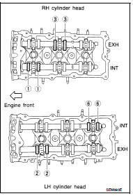
5. Set No.1 cylinder at TDC on its compression stroke.
• Align pointer with TDC mark on crankshaft pulley.
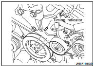
• Check that the valve lifters on No.1 cylinder are loose and valve lifters on No.4 are tight. If not, turn the crankshaft one full revolution (360°) and align as shown.
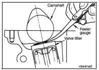
6. Check only the valves as shown.
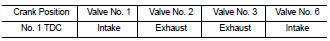
• Using a feeler gauge, measure the clearance between the valve lifter and camshaft.
• Record any valve clearance measurements which are out of specification. They will be used later to determine the required replacement lifter size.
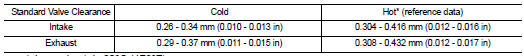
Valve Clearance for Checking (cold)
Intake : 0.26 - 0.34 mm (0.010 - 0.013 in)
Exhaust : 0.29 - 0.37 mm (0.011 - 0.015 in)
7. Turn crankshaft 240°.
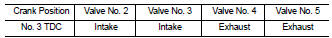
8. Set No.3 cylinder at TDC on its compression stroke.
9. Check only those valves as shown.
10. Turn the crankshaft 240° and align as above.
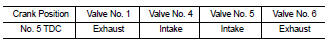
11. Set No.5 cylinder at TDC on its compression stroke.
12. Check only those valves as shown.
13. If all valve clearances are within specification, install the following components. If the valve clearances are out of specification, adjust the valve clearances.
• Intake manifold collectors
• Rocker covers
• All spark plugs
• All ignition coils
VALVE ADJUSTING
CAUTION: Adjust valve clearance while engine is cold.
NOTE: • Perform adjustment by selecting the correct head thickness of the valve lifter (adjusting shims are not used).
• The specified valve lifter thickness is the dimension at normal temperatures. Ignore dimensional differences caused by temperature. Use specifications for hot engine condition to confirm valve clearances.
1. Remove the camshaft.
2. Remove the valve lifter that was measured as being outside the standard specifications.
3. Measure the center thickness of the removed lifter with a micrometer, as shown.
4. Use the equation below to calculate the replacement valve lifter thickness.
Valve lifter thickness calculation equation: t = t1 + (C1 - C2) t = thickness of the replacement lifter
t1 = thickness of the removed lifter
C1 = measured valve clearance
C2 = standard valve clearance
• The thickness of the new valve lifter can be identified by the stamp mark on the reverse side (inside the lifter).
• Available thickness of the valve lifter (factory setting): 7.88 - 8.40 mm (0.3102 - 0.3307 in), in 0.02 mm (0.0008 in) increments, in 27 sizes (intake / exhaust). Refer to EM-231, "Cylinder Head".
5. Install the selected replacement valve lifter.
6. Install the camshaft.
7. Rotate the crankshaft a few turns by hand.
8. Confirm that the valve clearances are within specification.
9. After the engine has been run to full operating temperature, confirm that the valve clearances are within specification.
* Approximately 80°C (176°F)
 Air cleaner filter
 Compression pressure