Nissan Altima (L32) 2007-2012 Service Manual: Clutch fluid
Air Bleeding Procedure
CAUTION: Do not spill clutch fluid onto painted surfaces. If it spills, wipe up immediately and wash the affected area with water. NOTE: • Do not use a vacuum assist or any other type of power bleeder on this system. Use of vacuum assist or power bleeder will not purge all the air from the system.
• Carefully monitor clutch fluid level in reservoir tank during bleeding operation.
• First bleed the air from the bleeding connector on the CSC and then from the air bleed connector valve.
1. Fill master cylinder reservoir tank with new clutch fluid.
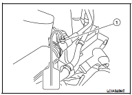
2. Connect a transparent vinyl tube and container to the bleeding connector (1) on the CSC.
3. Depress and release the clutch pedal slowly and fully 15 times at an interval of two to three seconds and release the clutch pedal.

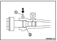
4. Bleed the air from the clutch system according to the following: 1. Push in the lock pin (1) of the bleeding connector (2), and hold it in.
CAUTION: Hold the lock pin in to prevent the bleeding connector from separating when fluid pressure is applied.

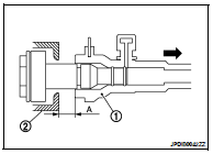
2. Slide the bleeding connector (1) away from the transaxle housing (2) to the specified distance (A) to allow air to bleed from the clutch system.


3. Depress the clutch pedal and hold it down.
CAUTION: Hold the clutch pedal down to prevent air from getting back into the clutch system.
5. Return the bleeding connector and lock pin to their original positions.
6. Release the clutch pedal and wait for five seconds.
7. Repeat steps 3 through 6 until no air bubbles can be observed in the clutch fluid.
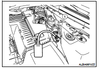
8. Connect a transparent vinyl tube and container to the air bleed connector valve (1).
9. Fully depress the clutch pedal several times.
10. With clutch pedal depressed, open the air bleed connector valve.
11. Close the air bleed connector valve.
12. Release the clutch pedal and wait for five seconds.
13. Repeat steps 9 through 12 until no air bubble can be observed in the clutch fluid.
14. Check clutch fluid level in reservoir tank.


 Clutch pedal
 On-vehicle repair