Nissan Altima (L32) 2007-2012 Service Manual: Collision diagnosis
For Frontal Collision
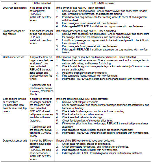
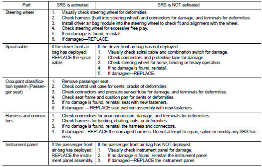
Check the SRS components using the following table.
• After the work is completed, perform self-diagnosis to check that no malfunction is detected. Refer to SRC- 12, "SRS Operation Check".
SRS INSPECTION (FOR FRONTAL COLLISION)
For Side and Rollover Collision
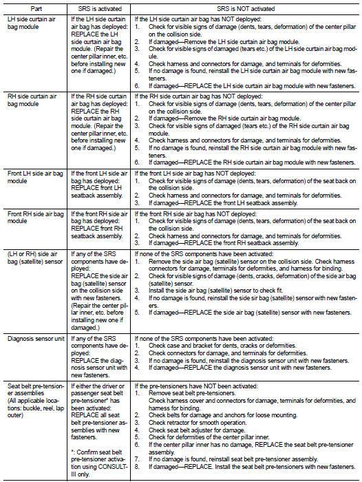
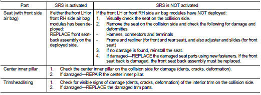
Check the SRS components using the following table.
• After the work is completed, perform self-diagnosis to check that no malfunction is detected. Refer to SRC- 12, "SRS Operation Check".
WHEN SRS IS ACTIVATED IN THE SIDE OR ROLLOVER COLLISION
1. Replace the following components: - Front seat back assembly (on the side on which side air bag is activated) - Diagnosis sensor unit - (LH or RH) side air bag (satellite) sensor (on the side on which side air bag is activated) 2. Check the SRS components and the related parts using the following table.
- Replace any SRS components and the related parts showing visible signs of damage (dents, cracks, deformation).
3. Conduct self-diagnosis using CONSULT-III and “AIR BAG” warning lamp. Refer to SRC-12, "SRS Operation Check" for details. Make sure entire SRS operates properly.
WHEN SRS IS NOT ACTIVATED IN THE SIDE OR ROLLOVER COLLISION
1. Check the SRS components and the related parts using the following table.
- If the front seat back assembly is damaged, the front seat back assembly must be replaced.
2. Conduct self-diagnosis using CONSULT-III and “AIR BAG” warning lamp. Refer to SRC-12, "SRS Operation Check" for details. Make sure entire SRS operates properly.
SRS INSPECTION (FOR SIDE AND ROLLOVER COLLISION)
 Occupant classification system
control unit
Occupant classification system
control unit SRS Airbag control system