Nissan Altima (L32) 2007-2012 Service Manual: Combination switch input circuit
Diagnosis Procedure
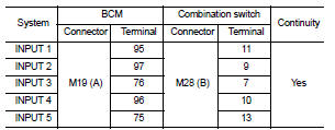
1. CHECK INPUT 1 - 5 SYSTEM CIRCUIT FOR OPEN
1. Turn the ignition switch OFF.
2. Disconnect the BCM and combination switch.
3. Check continuity between BCM harness connector and combination
switch harness connector.
Does continuity exist?
YES >> GO TO 2
NO >> Repair or replace harness.
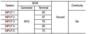
2. CHECK INPUT 1 - 5 SYSTEM CIRCUIT FOR SHORT
Check for continuity between BCM harness connector and ground.
Does continuity exist?
YES >> Repair or replace harness.
NO >> GO TO 3
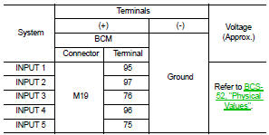
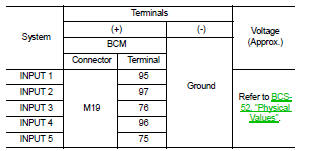
3. CHECK BCM OUTPUT VOLTAGE
1. Connect the BCM.
2. Check voltage between BCM harness connector and ground.
Is the measurement normal?
YES >> GO TO 4
NO >> Replace BCM. Refer to BCS-96, "Removal and Installation".
4. CHECK BCM INPUT SIGNAL
1. Connect the combination switch.
2. Turn ON any switch in the system that is malfunctioning.
3. Check voltage between BCM harness connector and ground.
Is the measurement normal when any of the switches is turned ON?
YES >> Replace BCM. Refer to BCS-96, "Removal and Installation".
NO >> Replace the combination switch. Refer to WW-121, "Removal and
Installation".
Special Repair Requirement
1. REQUIRED WORK WHEN REPLACING BCM
Initialize control unit. Refer to BCS-6, "CONFIGURATION (BCM) : Special
Repair Requirement".
>> Work End.
Diagnosis Procedure
1. CHECK FUSE AND FUSIBLE LINK
Check if the following BCM fuse or fusible link are blown.
Is the fuse or fusible link blown?
YES >> Replace the blown fuse or fusible li ...
Diagnosis Procedure
1. CHECK OUTPUT 1 - 5 SYSTEM CIRCUIT FOR OPEN
1. Turn the ignition switch OFF.
2. Disconnect the BCM and combination switch.
3. Check continuity between BCM harness connect ...
Other materials: Wireless charger (if so equipped)
Indicator
Charging pad
The wireless charger is located on the front
of the center console. Lay the smartphone
on the pad of the wireless charger. Charging
will start automatically. The smartphone
will be charged continuously while
the ignition switch is in the ON position.
NOTE:
The wireless ch ...
Booster seats
For additional information on installing a
booster seat in your vehicle, follow the instructions
outlined in this section.
Precautions on booster seats
WARNING
If a booster seat and seat belt are not
used properly, the risk of a child being
injured or killed in a sudden stop or collision
greatly inc ...
Vehicle information display warnings
and indicators
The following messages may appear in
your vehicle information display.
Place the key near the start
switch
This indicator appears when the battery of
the Intelligent Key is low and when the Intelligent
Key system and the vehicle are not
communicating normally.
If this appears, touch the ignition s ...
 Power supply and ground circuit
 Combination switch output circuit