Nissan Altima (L32) 2007-2012 Service Manual: Communication signal circuit (coupe)
SATELLITE RADIO TUNER
Description
Communication signals are exchanged between the audio unit and satellite radio tuner using the communication circuits.
Diagnosis Procedure
1.CHECK HARNESS - 1
1. Turn ignition switch OFF.
2. Disconnect satellite radio tuner (factory installed) connector B57 and audio unit connector M45.
3. Check continuity between satellite radio tuner (factory installed) harness connector B57 (A) terminal 28 and audio unit harness connector M45 (B) terminal 38.

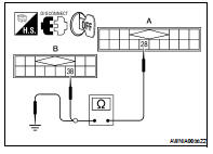
4. Check continuity between satellite radio tuner (factory installed) harness connector B57 (A) terminal 28 and ground.

Are continuity results as specified? YES >> GO TO 2
NO >> Repair harness or connector.
2.CHECK HARNESS - 2
1. Check continuity between satellite radio tuner (factory installed) harness connector B57 (A) terminal 29 and audio unit harness connector M45 (B) terminal 39.

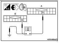
2. Check continuity between satellite radio tuner (factory installed) harness connector B57 (A) terminal 29 and ground.

Are continuity results as specified? YES >> GO TO 3
NO >> Repair harness or connector.
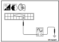
3.CHECK HARNESS - 3
1. Check continuity between satellite radio tuner (factory installed) harness connector B57 (A) terminal 30 and audio unit harness connector M45 (B) terminal 40.

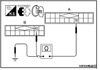
2. Check continuity between satellite radio tuner (factory installed) harness connector B57 (A) terminal 30 and ground.

Are continuity results as specified? YES >> GO TO 4
NO >> Repair harness or connector.
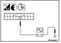
4.CHECK REQ1 SIGNAL
1. Connect satellite radio tuner (factory installed) connector and audio unit connector.
2. Turn ignition switch to ACC
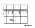
3. Check signal between satellite radio tuner (factory installed) harness connector B57 terminal 28 and ground with CONSULT-III or oscilloscope.
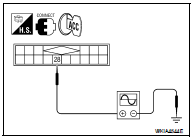

Are voltage readings as specified? YES >> GO TO 5
NO >> Replace audio unit. Refer to AV-72, "Removal and Installation".
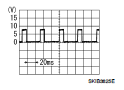
5.CHECK TXD SIGNAL
Check signal between satellite radio tuner (factory installed) harness connector B57 terminal 29 and ground with CONSULT-III or oscilloscope.

Are the voltage readings as specified? YES >> GO TO 6
NO >> Replace satellite radio tuner. Refer to AV-76, "Removal and Installation - Coupe".
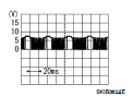
6.CHECK RXD SIGNAL
Check signal between satellite radio tuner (factory installed) harness connector B57 terminal 30 and ground with CONSULT-III or oscilloscope.

Are the voltage readings as specified? YES >> Replace satellite radio tuner. Refer to AV-76, "Removal and Installation - Coupe".
NO >> Replace audio unit. Refer to AV-72, "Removal and Installation".
 Steering switch
 Communication signal circuit (sedan)