Nissan Altima (L32) 2007-2012 Service Manual: Control cable
Exploded View
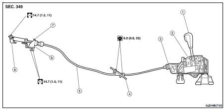
1. Control lever
2. Control device assembly
3. Control cable socket
4. Retainer grommet
5. Control cable
6. Bracket
7. Lock plate
8. Manual lever
Removal and Installation
REMOVAL
1. Shift control lever to "P".
2. Remove the air filter assembly. Refer to EM-25, "Removal and Installation".
3. Remove the control cable nut and control cable form the manual lever.
4. Remove the lock plate and the control cable from the bracket.
5. Remove the center console. Refer to IP-12, "Removal and Installation".
6. Remove the bracket covering the retainer grommet.
7. Remove the retainer grommet bolts and the retainer grommet.
8. Remove the control cable from the control device assembly.
9. Remove the control cable from the vehicle.
INSTALLATION
Installation is in the reverse order of removal.
• When installing the control cable to the control device assembly, make sure
that the control cable socket is
fully pressed into the control device assembly, and the control cable end is
fully pressed in with the ribbed
surface facing upward.
• After installation is complete, adjust and check the CVT position. Refer to
TM-432, "Inspection and Adjustment".
Exploded View
1. Control lever knob
2. Lock pin
3. Knob cover
4. Control device selector plate
5. Control device assembly
Removal and Installation
REMOVAL
1. Remove the center console assemb ...
 Control device
 Differential side oil seal