Nissan Altima (L32) 2007-2012 Service Manual: Control device
Exploded View
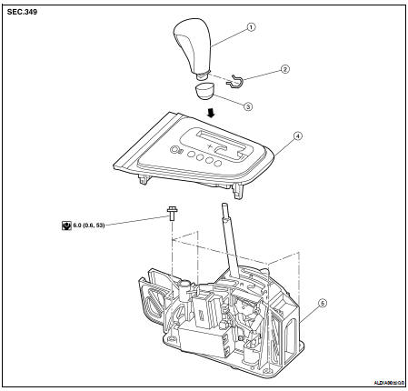
1. Control lever knob
2. Lock pin
3. Knob cover
4. Control device selector plate
5. Control device assembly
Removal and Installation
REMOVAL
1. Remove the center console assembly. Refer to IP-12, "Removal and Installation".
2. Disconnect the control cable from the control device assembly.
3. Disconnect the CVT device harness connector from the control device assembly.
4. Remove the control device assembly bolts and the control device assembly.
INSTALLATION
Installation is in the reverse order of removal.
• When installing the control cable to the control device assembly, make sure that the control cable is fully pressed in with the ribbed surface facing upward.
• After installation is completed, adjust and check CVT position. Refer to TM-429, "Inspection and Adjustment".
Inspection and Adjustment
INSPECTION
1. Place selector lever in “P” position, and turn ignition switch ON (engine stop).
2. Make sure that selector lever can be shifted to other than “P” position when brake pedal is depressed.
Also make sure that selector lever can be shifted from “P” position only when brake pedal is depressed.
3. Move the selector lever and check for excessive effort, sticking, noise or rattle.
4. Confirm the selector lever stops at each position with the feel of engagement when it is moved through all the positions. Check that the actual position of the selector lever matches the position shown by the shift position indicator and the manual lever on the transaxle.
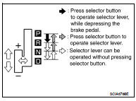
5. The method of operating the selector lever to individual positions correctly should be as shown.
6. When selector button is pressed in “P”, “R”, or “N” position without applying forward/backward force to selector lever, check button operation for sticking.
7. Confirm the back-up lamps illuminate only when selector lever is placed in the “R” position. Confirm the back-up lamps do not illuminate when the selector lever is pushed toward the “R” position when in the “P” or “N” position.
8. Confirm the engine can only be started with the selector lever in the “P” and “N” positions.
9. Make sure transaxle is locked completely in “P” position.
10. When selector lever is set to manual shift gate, make sure that manual mode is displayed on combination meter.
Shift selector lever to “+” and “-” sides, and check that set shift position changes.
ADJUSTMENT
CAUTION: Apply parking brake before adjustment.
1. Loosen the control cable nut.
2. Place the manual lever and the selector lever in “P” position.
3. Tighten control cable nut to specified torque.
Control cable nut: Refer to TM-433, "Exploded View".
CAUTION: Secure the manual lever when tightening control cable nut. Make sure the manual lever stays in the "P" position.
4. Check the operation of the CVT. Refer to TM-432, "Inspection and Adjustment".
 Transmission control module
 Control cable