Nissan Altima (L32) 2007-2012 Service Manual: Cooling fan
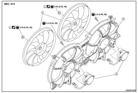
Removal and Installation
1. Fan blade
2. Fan shroud and motor assembly
REMOVAL
1. Drain engine coolant from the radiator. Refer to CO-12, "Changing Engine
Coolant".
CAUTION:
Perform when engine is cold.
2. Remove air cleaner duct assembly. Refer to EM-25, "Removal and
Installation".
3. Disconnect radiator upper hose.
4. Disconnect fan motor connectors.
5. Remove radiator cooling fan assembly.
INSTALLATION
Installation is in the reverse order of removal.
• After installation refill engine coolant and check for leaks. Refer to CO-12,
"Changing Engine Coolant" and
CO-11, "System Inspection".
CAUTION:
Do not spill coolant in engine compartment. Use a shop cloth to absorb coolant.
• Cooling fan is controlled by ECM. For details, refer to EC-613, "System
Description".
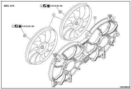
Disassembly and Assembly of Cooling Fan
1. Fan blade
2. Fan shroud
3. Fan motor
DISASSEMBLY
1. Remove fan blade nut.
2. Remove fan blade from fan motor.
3. Remove fan motor bolts and remove fan motor from fan shroud.
ASSEMBLY
Assembly is in the reverse order of disassembly.
Removal and Installation
1. Radiator
2. CVT oil cooler hose (if equipped)
3. Radiator hose (upper)
4. Radiator hose (lower)
5. Cooling fan
6. Reservoir tank
7. Reservoir hose
8. Radiator fil ...
Removal and Installation
1. Water pump
2. Gaskets
3. Water pump housing
4. Water pipe
5. O-ring
WARNING:
Never remove the radiator cap when the engine is hot. Serious burns could occur
from ...
Other materials: Interior lights
The interior light can be turned on regardless
of door position. The light will
go off after a period of time unless the
ignition switch is placed in the ON position
when any door is opened.
The interior lights can be set to operate
when the doors are opened. To turn off
the interior light ...
Three-point type seat belt with
retractor
WARNING
Every person who drives or rides in
this vehicle should use a seat belt at
all times. Children should be in the
rear seats and in an appropriate
restraint.
Do not ride in a moving vehicle when
the seatback is reclined. This can be
dangerous. The shoulder belt will not
be against yo ...
Front manual seat adjustment
(if so equipped)
Your vehicle seats can be adjusted manually.
For additional information about adjusting
the seats, refer to the steps outlined
in this section.
WARNING
Before driving the vehicle, return the
seatback to an upright seating position
after manually releasing it. Also, make
sure the seat is locked in p ...
 Radiator
 Water pump