Nissan Altima (L32) 2007-2012 Service Manual: Water pump
Removal and Installation
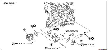
1. Water pump
2. Gaskets
3. Water pump housing
4. Water pipe
5. O-ring
WARNING: Never remove the radiator cap when the engine is hot. Serious burns could occur from high pressure coolant escaping from the radiator.
CAUTION: • When removing water pump assembly, be careful not to get coolant on drive belt.
• Water pump cannot be disassembled and should be replaced as a unit.
• After installing water pump, connect hose and clamp securely, then check for leaks using radiator cap tester.
REMOVAL
1. Drain engine coolant from the radiator. Refer to CO-12, "Changing Engine Coolant".
CAUTION: Perform when the engine is cold.
2. Remove drive belt. Refer to EM-16, "Removal and Installation".
3. Remove engine cover using power tools.
4. Remove generator. Refer to CHG-27, "Removal and Installation".
5. Remove RH wheel and tire assembly. Refer to WT-66, "Adjustment".
6. Remove fender protector RH. Refer to EXT-19, "Removal and Installation" (Coupe models) or EXT-40, "Removal and Installation" (Sedan models).
7. Remove engine ground strap.
8. Remove the water pump.
CAUTION: • Handle the water pump vane so that it does not contact any other parts.
• Water pump cannot be disassembled and should be replaced as an assembly.
NOTE: If it is necessary to remove the water pipe, the exhaust manifold and three way catalyst assembly must be removed. Refer to EM-30, "Removal and Installation".
INSPECTION AFTER REMOVAL
• Visually check that there is no significant dirt or rusting on the water pump body and vane.
• Check that there is no looseness in the vane shaft, and that it turns smoothly when rotated by hand.
• If the water pump does not perform properly, replace the water pump assembly.
INSTALLATION
Installation is in the reverse order of removal.
• When inserting water pipe end to cylinder block, apply a neutral detergent to O-ring. Then insert it immediately.
INSPECTION AFTER INSTALLATION
• After installation refill engine coolant and check for leaks. Refer to CO-12, "Changing Engine Coolant" and CO-11, "System Inspection".
 Cooling fan
 Thermostat and thermostat housing