Nissan Altima (L32) 2007-2012 Service Manual: CVT system
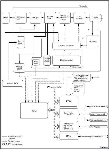
System Diagram
Component Parts Location - Coupe
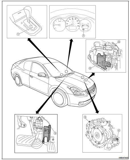
1. Control device assembly (Manual
mode select switch and manual
mode position select switch)
2. Accelerator pedal position (APP)
sensor
3. Secondary speed sensor
4. CVT unit harness connector
5. TCM
6. Battery
7. Shift position indicator
Manual mode indicator
Component Parts Location - Sedan
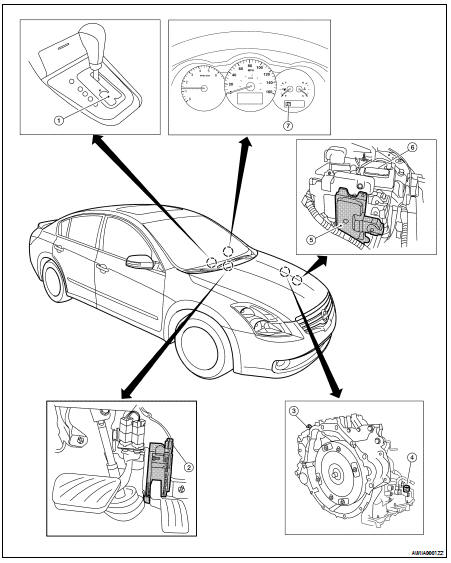
1. Control device assembly (Manual
mode select switch and manual
mode position select switch)
2. Accelerator pedal position (APP)
sensor
3. Secondary speed sensor
4. CVT unit harness connector
5. TCM
6. Battery
7. Shift position indicator
Manual mode indicator
Cross-Sectional View
1. Converter housing
2. Oil pump
3. Forward clutch
4. Reverse brake
5. Planetary carrier
6. Primary pulley
7. Steel belt
8. Sun gear
9. Side cover
10. Internal gear
1 ...
 Function diagnosis
 Mechanical system