Nissan Altima (L32) 2007-2012 Service Manual: Mechanical system
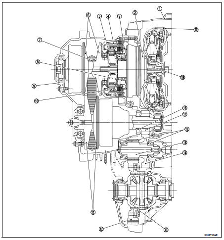
Cross-Sectional View
1. Converter housing
2. Oil pump
3. Forward clutch
4. Reverse brake
5. Planetary carrier
6. Primary pulley
7. Steel belt
8. Sun gear
9. Side cover
10. Internal gear
11. Secondary pulley
12. Final gear
13. Differential case
14. Idler gear
15. Reduction gear
16. Taper roller bearing
17. Output gear
18. Parking gear
19. Input shaft
20. Torque converter
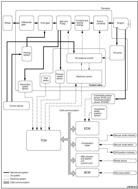
System Diagram
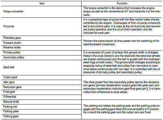
System Description
Transmits the power from the engine to the drive wheel.
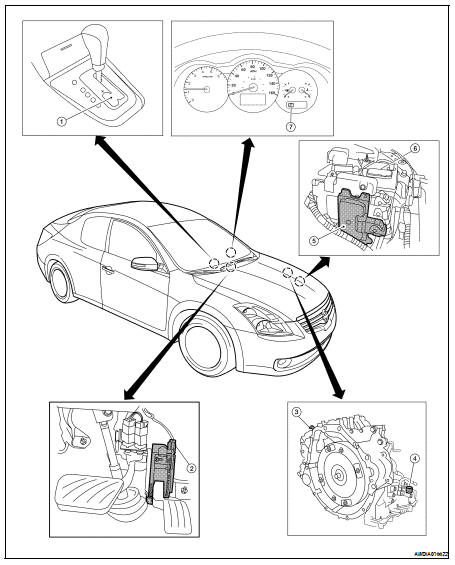
Component Parts Location - Coupe
1. Control device assembly (Manual
mode select switch and manual
mode position select switch)
2. Accelerator pedal position (APP)
sensor
3. Secondary speed sensor
4. CVT unit harness connector
5. TCM
6. Battery
7. Shift position indicator
Manual mode indicator
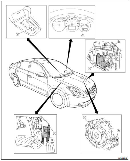
Component Parts Location - Sedan
1. Control device assembly (Manual
mode select switch and manual
mode position select switch)
2. Accelerator pedal position (APP)
sensor
3. Secondary speed sensor
4. CVT unit harness connector
5. TCM
6. Battery
7. Shift position indicator
Manual mode indicator
Component Description
System Diagram
Component Parts Location - Coupe
1. Control device assembly (Manual
mode select switch and manual
mode position select switch)
2. Accelerator pedal position (APP)
sensor
3. S ...
System Diagram
System Description
The hydraulic control mechanism consists of the oil pump directly driven by
the engine, the hydraulic control
valve that controls line pressure and transmissi ...
Other materials: Front manual seat adjustment
(if so equipped)
Your vehicle seats can be adjusted manually.
For additional information about adjusting
the seats, refer to the steps outlined
in this section.
WARNING
Before driving the vehicle, return the
seatback to an upright seating position
after manually releasing it. Also, make
sure the seat is locked in p ...
Forward-facing child restraint
installation using the seat belts
WARNING
The three-point seat belt with Automatic
Locking Retractor (ALR) must be
used when installing a child restraint.
Failure to use the ALR mode will result
in the child restraint not being properly
secured. The restraint could tip over or
be loose and cause injury to a child in a
sudden stop o ...
Precautions on child restraints
WARNING
Failure to follow the warnings and instructions
for proper use and installation
of child restraints could result in serious
injury or death of a child or other
passengers in a sudden stop or collision:
The child restraint must be used
and installed properly. Always follow
all of ...
 CVT system
 Hydraulic control system