Nissan Altima (L32) 2007-2012 Service Manual: Diagnosis system (IPDM E/R)
Diagnosis Description
AUTO ACTIVE TEST
Description
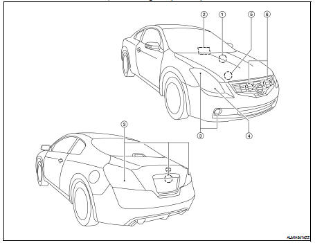
In auto active test mode, the IPDM E/R sends a drive signal to the following systems to check their operation.
• Oil pressure warning lamp
• Front wiper (LO, HI)
• Parking lamps
• License plate lamps
• Tail lamps
• Front fog lamps (if equipped)
• Headlamps (LO, HI)
• A/C compressor (magnet clutch)
• Cooling fans
Operation Procedure
1. Close the hood and lift the wiper arms from the windshield. (Prevent windshield damage due to wiper operation) NOTE: When auto active test is performed with hood opened, sprinkle water on windshield beforehand.
2. Turn ignition switch OFF.
3. Turn the ignition switch ON, and within 20 seconds, press the front door switch LH 10 times. Then turn the ignition switch OFF.
CAUTION: Close front door RH. 4. Turn the ignition switch ON within 10 seconds. After that the horn sounds once and the auto active test starts.
5. The oil pressure warning lamp starts blinking when the auto active test starts.
6. After a series of the following operations is repeated 3 times, auto active test is completed.
NOTE: When auto active test mode has to be cancelled halfway through test, turn ignition switch OFF.
CAUTION: • If auto active test mode cannot be actuated, check door switch system. Refer to DLK-69, "Component Function Check".
• Do not start the engine.
Inspection in Auto Active Test Mode
When auto active test mode is actuated, the following 6 steps are repeated 3 times.
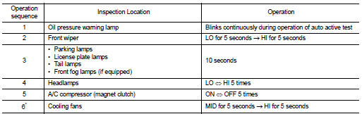
*: Outputs duty ratio of 50% for 5 seconds → duty ratio of 100% for 5 seconds on the cooling fan control module.
Concept of auto active test
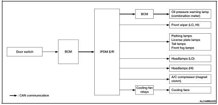
• IPDM E/R starts the auto active test with the door switch signals transmitted by BCM via CAN communication.
Therefore, the CAN communication line between IPDM E/R and BCM is considered normal if the auto active test starts successfully.
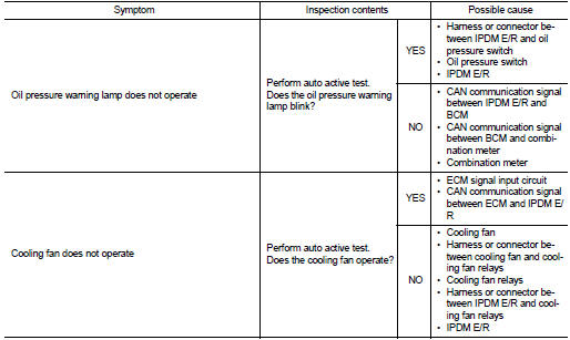
• The auto active test facilitates troubleshooting if any systems controlled by IPDM E/R cannot be operated.
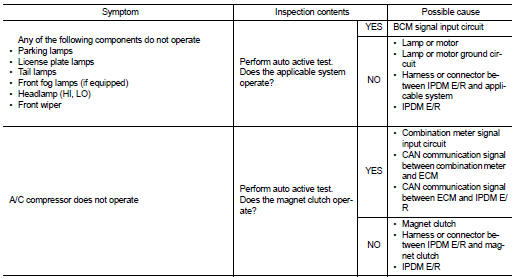
Diagnosis chart in auto active test mode
CONSULT - III Function (IPDM E/R)
APPLICATION ITEM
CONSULT-III performs the following functions via CAN communication with IPDM E/R.
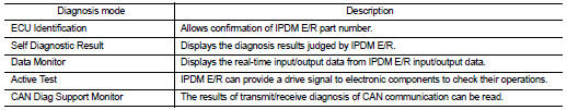
SELF DIAGNOSTIC
Refer to PCS-45, "DTC Index".
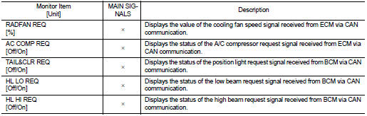
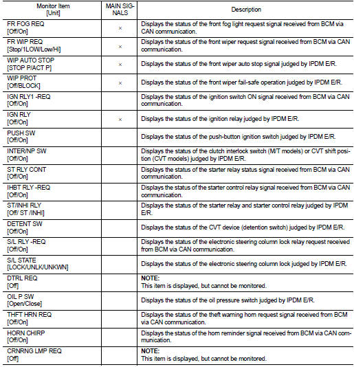
DATA MONITOR
Monitor item
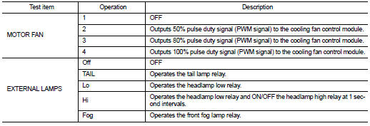
ACTIVE TEST
Test item
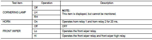
 Wiper
Wiper Component diagnosis