Nissan Altima (L32) 2007-2012 Service Manual: Diagnosis system (meter)
Diagnosis Description
SELF-DIAGNOSIS MODE
• Odo/trip meter and information display segment operation can be checked in self-diagnosis mode.
• Meters/gauges can be checked in self-diagnosis mode.
OPERATION PROCEDURE
1. Turn the ignition switch OFF.
2. While pushing the odo/trip meter switch, turn the ignition switch ON again.
3. Push the odo/trip meter switch at least 3 times within 7 seconds after the ignition switch is turned ON.
4. The unified meter control unit is turned to self-diagnosis mode.
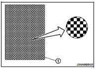
• All the segments on the odo/trip meter illuminate.
• Dots in all segments of information display LCD (1) flash alternately.
NOTE: If any of the segments are not displayed, replace the combination meter. Refer to MWI-176, "Removal and Installation".
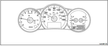
5. Push the odo/trip meter switch. Each meter/gauge should indicate as shown in the figure.
CONSULT-III Function (METER/M&A)
CONSULT-III can display each diagnostic item using the diagnostic test modes shown following.
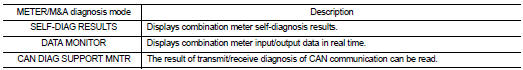
SELF-DIAG RESULTS
Display Item List
Refer to MWI-95, "DTC Index".
DATA MONITOR
Display Item List
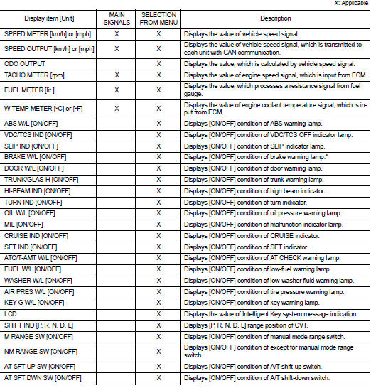
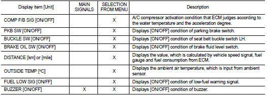
NOTE: Some items are not available due to vehicle specification.
*: The monitor will indicate “OFF” even though the brake warning lamp is on if either of the following conditions exist.
• The parking brake is engaged
• The brake fluid level is low
 Compass
 Component diagnosis