Nissan Altima (L32) 2007-2012 Service Manual: Drive belts
Checking Drive Belts
WARNING: Inspect the drive belt only when the engine is stopped.
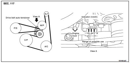
• Make sure that the stamp mark of drive belt auto-tensioner is within the usable range.
NOTE: • Check the drive belt auto-tensioner indicator (notch) when the engine is cold.
• When the new drive belt is installed, the range should be (A) as shown.
• Visually check entire belt for wear, damage or cracks.
• If the indicator is out of allowable use range or belt is damaged, replace the belt.
Tension Adjustment
• Belt tension is not manually adjustable, it is automatically adjusted by the drive belt auto-tensioner.
Removal and Installation
REMOVAL
1. Remove the fender protector side cover RH. Refer to EXT-19, "Removal and Installation" (Coupe models) or EXT-40, "Removal and Installation" (Sedan models).
2. Securely hold the hexagonal part in pulley center of drive belt auto-tensioner, move in the direction of arrow (loosening direction of tensioner) using Tool.
Tool number : — (J-46535)
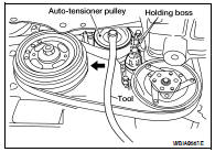
WARNING: • Avoid placing hand in a location where pinching may occur if the holding tool accidentally comes off.
CAUTION: • Do not loosen the auto-tensioner pulley bolt. (Do not turn it counterclockwise.) If turned counterclockwise, the complete auto-tensioner must be replaced as a unit, including pulley.
3. Insert a rod approximately 6 mm (0.24 in) in diameter through the rear of tensioner into retaining boss to lock tensioner pulley.
• Leave tensioner pulley arm locked until drive belt is installed again.
4. Loosen drive belt from water pump pulley and then remove it from the other pulleys.
INSTALLATION
1. Install the drive belt onto all of the pulleys except for the water pump pulley. Then install the drive belt onto water pump pulley last.
CAUTION: Confirm belts are completely set on the pulleys.
2. Release tensioner, and apply tension to drive belt.
WARNING: • Avoid placing hand in a location where pinching may occur if the holding tool accidentally comes off.
CAUTION: • Do not loosen the auto-tensioner pulley bolt. Don't turn it counterclockwise. If turned counterclockwise, the complete auto-tensioner must be replaced as a unit, including pulley.
3. Turn crankshaft pulley clockwise several times to equalize tension between each pulley.
4. Confirm tension of drive belt at indicator is within the allowable use range. Refer to EM-16, "Checking Drive Belts".
Removal and Installation of Drive Belt Auto-tensioner
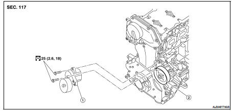
1. Drive belt auto-tensioner
2. Water pump pulley
REMOVAL
CAUTION: The complete auto-tensioner must be replaced as a unit, including the pulley.
1. Remove the front RH wheel and tire assembly. Refer to WT-66, "Adjustment".
2. Remove the fender protector side cover. Refer to EXT-19, "Removal and Installation" (Coupe models) or EXT-40, "Removal and Installation" (Sedan models).
3. Remove the drive belt. Refer to EM-16, "Removal and Installation".
• Insert a rod approximately 6 mm (0.24 in) in diameter through the rear of tensioner into the retaining boss to lock tensioner pulley.
4. Remove power steering reservoir and position aside. Refer to ST-19, "QR25DE : Exploded View".
5. Support the engine with a suitable tool.
6. Remove RH engine mounting bracket, mounting insulator and support bracket. Refer to EM-72, "Removal and Installation".
7. Remove the drive belt auto-tensioner, with power tool.
CAUTION: Do not loosen the auto-tensioner pulley bolt. (Don't turn it counterclockwise.) If turned counterclockwise, the complete auto-tensioner must be replaced as a unit, including pulley.
INSTALLATION
Installation is in the reverse order of removal.
CAUTION: • If there is damage greater than peeled paint, replace drive belt auto-tensioner units.
• Install the drive belt auto-tensioner carefully so not to damage the water pump pulley.
• Do not swap the pulley between the new and old auto-tensioner units.
 Spark plug
 Air cleaner filter