Nissan Altima (L32) 2007-2012 Service Manual: Driver air bag module
Exploded View
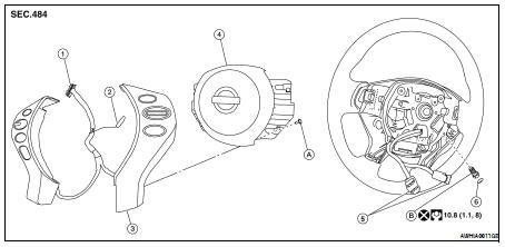
1. Steering switch connector
2. Steering switch ground connector
3. Steering switches
4. Driver air bag module
5. Driver air bag module connectors
6. Side lid (RH/LH)
A. Steering switch screw
B. Driver air bag module bolt (RH/LH)
Removal and Installation
REMOVAL
CAUTION: • Before servicing, turn ignition switch OFF, disconnect both battery terminals and wait at least three minutes.
• Do not use air tools or electric tools for servicing.
• Always work from the side of air bag module. Do not work from the front of it.
• Always place air bag module with pad side facing upward.
• Do not use old bolts after removal; replace with new bolts.
• Do not cause impact to the air bag module by dropping etc. Replace the air bag module if it has been dropped or sustained an impact.
1. Disconnect the negative and positive battery terminals, then wait at least three minutes.
2. Remove side lids, then remove the driver air bag module bolts (RH/LH).
3. Raise driver air bag module away from the steering wheel, then disconnect the steering switches.
4. Disconnect the driver air bag module connectors, then remove driver air bag module from steering wheel.
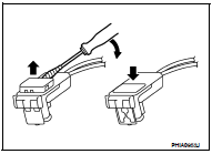
• For installing/removing direct-connect SRS connectors, refer to SRC-9, "Direct-connect SRS Component Connectors".
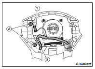
5. Disconnect the steering switch ground connector (1), then release the harness (2) from the clips.
6. Remove the steering switch screws (RH/LH) (A), then remove the steering switches from driver air bag module.
INSTALLATION
1. Attach steering switches (RH/LH) to driver air bag module.
2. Place the driver air bag module near the steering wheel and attach connectors (A).
3. Lift the driver air bag module while rotating counterclockwise into position over steering wheel.
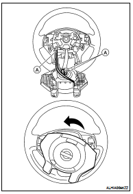
4. Pulling down on the steering switch harness, install the air bag module into the steering wheel.
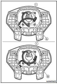
• Make sure that the steering switch harness is routed below the center of the air bag module inflator (1) as shown (B), and is not routed so it is pinched between the driver air bag module inflator (1) and steering column shaft threads as shown (A).
CAUTION: Make sure the steering switch harness is correctly routed below the center of the driver air bag module inflator (1) as shown (B), and NOT incorrectly routed across the driver air bag module inflator as shown (A).
5. Install the remaining components in the reverse order of removal. CAUTION: • Be careful not to damage or pinch the harness while installing.
• Tighten the driver air bag module bolts after centering the holes between the driver air bag module and the steering wheel horn contact bracket. If the holes are misaligned, the bolt threads may become damaged and the module will not install securely.
• After the work is completed, make sure no system malfunction is detected by air bag warning lamp.
• In case a malfunction is detected by the air bag warning lamp, reset by the self-diagnosis function and delete the memory by CONSULT–III.
• If a malfunction is still detected after the above operation, perform self-diagnosis to repair malfunctions.
Refer to SRC-12, "SRS Operation Check".
 On-vehicle repair
 Spiral cable