Nissan Altima (L32) 2007-2012 Service Manual: Ecu diagnosis
TCM
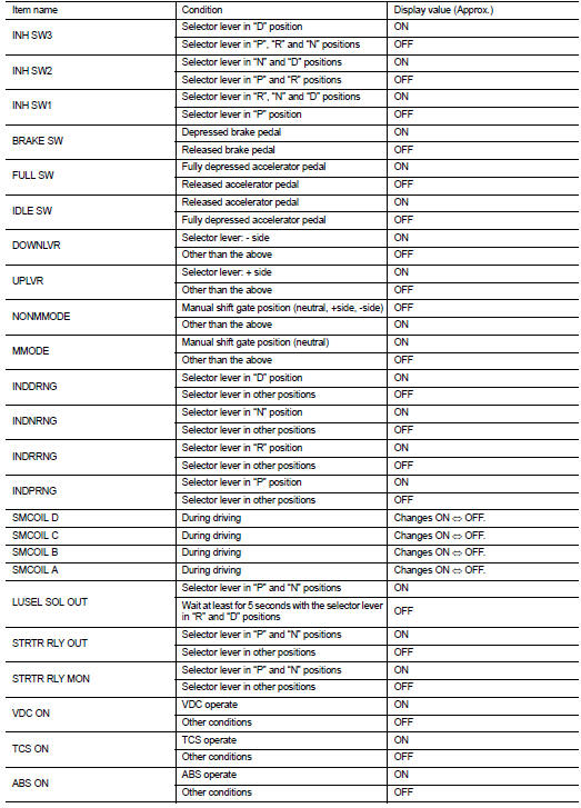
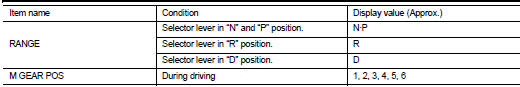
Reference Value
VALUES ON THE DIAGNOSIS TOOL
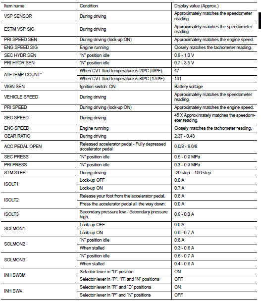
* Means CVT fluid temperature. Actual oil temperature °C (°F) cannot be checked unless a numeric value is converted. Refer to TM-237, "ATFTEMP COUNT Conversion Table".
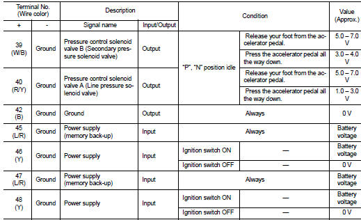
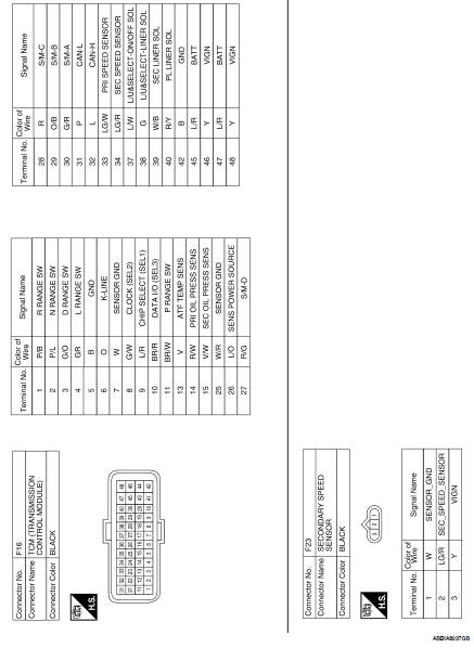
TERMINAL LAYOUT

PHYSICAL VALUES
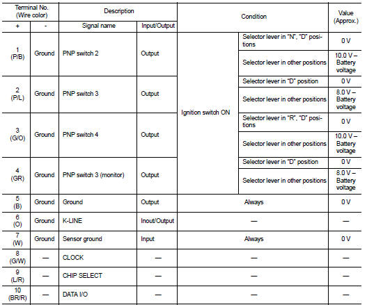
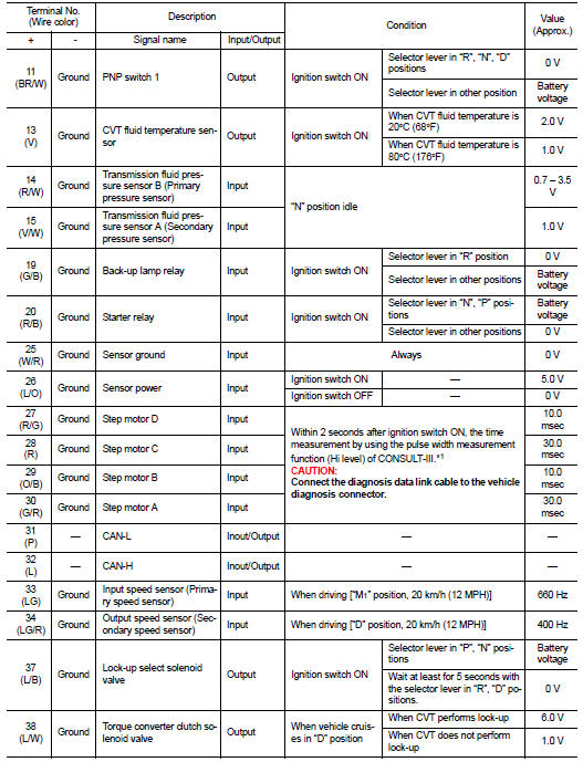
*1: A circuit tester cannot be used to test this item.
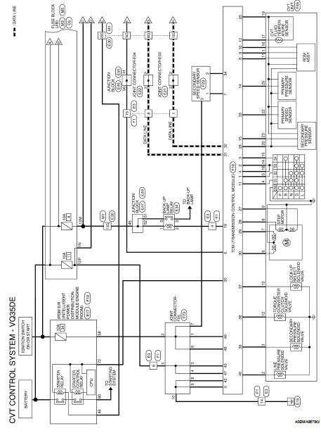
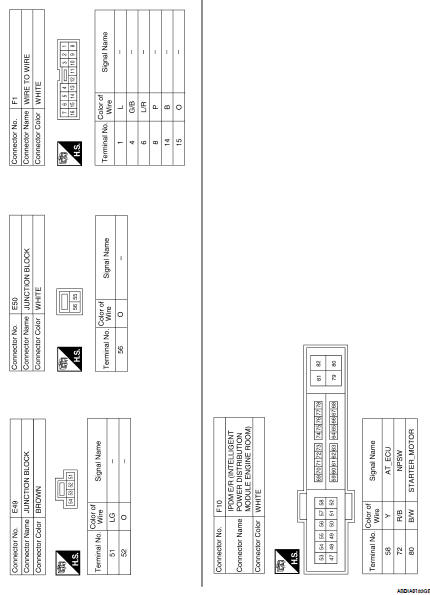
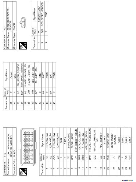
Wiring Diagram—CVT CONTROL SYSTEM— Coupe
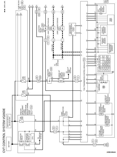
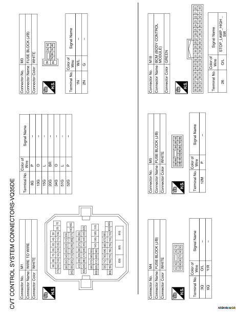
Wiring Diagram—CVT CONTROL SYSTEM—Sedan
Fail-safe
The TCM has an electrical fail-safe mode. This mode makes it possible to operate even if there is an error in a main electronic control input/output signal circuit.
FAIL-SAFE FUNCTION
If any malfunction occurs in a sensor or solenoid, this function controls the CVT to make driving possible.
Output Speed Sensor (Secondary Speed Sensor)
The shift pattern is changed in accordance with throttle position when an unexpected signal is sent from the output speed sensor (secondary speed sensor) to the TCM. The manual mode position is inhibited, and the transaxle is put in “D”.
Input Speed Sensor (Primary Speed Sensor)
The shift pattern is changed in accordance with throttle position and secondary speed (vehicle speed) when an unexpected signal is sent from the input speed sensor (primary speed sensor) to the TCM. The manual mode position is inhibited, and the transaxle is put in “D”.
PNP Switch
If an unexpected signal is sent from the PNP switch to the TCM, the transaxle is put in “D”.
Manual Mode Switch
If an unexpected signal is sent from the manual mode switch to the TCM, the transaxle is put in “D”.
CVT Fluid Temperature Sensor
If an unexpected signal is sent from the CVT fluid temperature sensor to the TCM, the gear ratio in use before receiving the unexpected signal is maintained or the gear ratio is controlled to keep engine speed under 2,800 rpm.
Transmission Fluid Pressure Sensor A (Secondary Pressure Sensor)
• If an unexpected signal is sent from the transmission fluid pressure sensor A (secondary pressure sensor) to the TCM, the secondary pressure feedback control is stopped and the offset value obtained before the nonstandard condition occurs is used to control line pressure.
• If transmission fluid pressure sensor A (secondary pressure sensor) error signal is input to TCM, secondary pressure feedback control stops, but line pressure is controlled normally.
Pressure Control Solenoid A (Line Pressure Solenoid)
If an unexpected signal is sent from the solenoid to the TCM, the pressure control solenoid A (line pressure solenoid) is turned OFF to achieve the maximum fluid pressure.
Pressure Control Solenoid B (Secondary Pressure Solenoid)
If an unexpected signal is sent from the solenoid to the TCM, the pressure control solenoid B (secondary pressure solenoid) is turned OFF to achieve the maximum fluid pressure.
Torque Converter Clutch Solenoid
If an unexpected signal is sent from the solenoid to the TCM, the torque converter clutch solenoid is turned OFF to cancel the lock-up.
Step Motor
If an unexpected signal is sent from the step motor to the TCM, the step motor coil phases “A” through “D” are all turned OFF to hold the gear ratio used right before the non-standard condition occurred.
CVT Lock-up Select Solenoid
If an unexpected signal is sent from the solenoid to the TCM, the CVT lock-up select solenoid is turned OFF to cancel the lock-up.
TCM Power Supply (Memory Back-up)
Transaxle assembly is protected by limiting the engine torque when the memory back-up power supply (for controlling) from the battery is not supplied to TCM. Normal statues is restored when turning the ignition switch OFF to ON after the normal power supply.
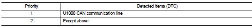
DTC Inspection Priority Chart
If some DTCs are displayed at the same time, perform inspections one by one based on the following priority chart.
NOTE: If DTC “U1000 CAN COMM CIRCUIT” is displayed with other DTCs, first perform the trouble diagnosis for “DTC U1000 CAN COMMUNICATION LINE”. Refer to TM-123.
DTC Index
NOTE: If DTC “U1000 CAN COMM CIRCUIT” is displayed with other DTCs, first perform the trouble diagnosis for “DTC U1000 CAN COMMUNICATION LINE”. Refer to TM-123.
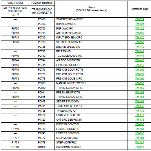
• *1: Refer to TM-117, "Diagnosis Description".
• *2: These numbers are prescribed by SAE J2012.
 Shift lock system
 Symptom diagnosis