Nissan Altima (L32) 2007-2012 Service Manual: Shift lock system
Description
The selector lever cannot be shifted from “P” position to any other position unless the ignition switch is in the ON position and the brake pedal is depressed.
Wiring Diagram - CVT SHIFT LOCK SYSTEM - Coupe
Wiring Diagram - CVT SHIFT LOCK SYSTEM - Sedan
Diagnosis Procedure
1. CHECK POWER SOURCE
1. Disconnect CVT device connector.
2. Turn ignition switch ON.
3. Check voltage between CVT device connector M23 terminal 6 and ground.
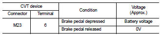
Is the inspection result normal? YES >> GO TO 5.
NO >> GO TO 2.
2. CHECK POWER SOURCE AT STOP LAMP SWITCH
1. Turn ignition switch OFF.
2. Disconnect stop lamp switch connector.
3. Turn ignition switch ON.
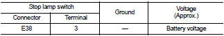
4. Check voltage between stop lamp switch connector E38 terminal 3 and ground.
Is the inspection result normal? YES >> GO TO 3.
NO >> Check the following: • Harness for short or open between fuse block (J/B) and stop lamp switch
• 10A fuse [No. 3, located in fuse block (J/B)]
3. CHECK STOP LAMP SWITCH
1. Turn ignition switch OFF.
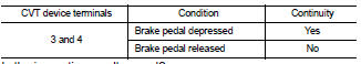
2. Check continuity between stop lamp switch terminals 3 and 4.
Is the inspection result normal? YES >> GO TO 4.
NO >> Replace stop lamp switch. Refer to BR-17, "Exploded View".
4. CHECK HARNESS BETWEEN STOP LAMP SWITCH AND CVT DEVICE FOR OPEN
Check continuity between stop lamp switch connector E38 (A) terminal 4 and CVT device connector M23 (B) terminal 6.
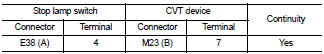
Is the inspection result normal? YES >> GO TO 5.
NO >> Repair harness or connectors.
5. CHECK GROUND CIRCUIT
1. Turn ignition switch OFF.
2. Check continuity between CVT device connector M23 terminal 7 and ground.

Is the inspection result normal? YES >> Replace CVT device. Refer to TM-255, "Removal and Installation".
NO >> Repair harness or connectors.
 P1778 step motor - function
 Ecu diagnosis