Nissan Altima (L32) 2007-2012 Service Manual: Engine control system
System Diagram
System Description
ECM performs various controls such as fuel injection control and ignition timing control.
Component Parts Location
1. Power valve actuator 1
2. Intake valve timing control solenoid valve (bank 1)
3. Power steering pressure sensor
4. Intake valve timing control solenoid valve (bank 2)
5. VIAS control solenoid valves 1 and 2
6. Fuel injector (bank 2)
7. Ignition coil (with power transistor) and spark plug (bank 2)
8. Crankshaft position sensor (POS)
9. Engine coolant temperature sensor
10. Camshaft position sensor (PHASE) (bank 2)
11. ECM
12. Refrigerant pressure sensor
13. Battery current sensor
14. PNP switch
15. Condenser-2
16. Mass air flow sensor (with intake air temperature sensor)
17. EVAP service port
18. Camshaft position sensor (PHASE) (bank 1)
19. Electric throttle control actuator
20. Power valve actuator 2
21. EVAP canister purge volume control solenoid valve
22. Ignition coil (with power transistor) and spark plug (bank 1)
23. Knock sensor
1. Mas air flow sensor (with intake air temperature sensor)
2. Air cleaner case
3. Engine coolant temperature sensor
4. EVAP canister purge volume control solenoid valve
5. Power valve actuator 1
6. VIAS control solenoid valve 1
7. VIAS control solenoid valve 2
8. Power valve actuator 2
9. Power steering pressure sensor
10. Tie rod (RH)
11. Power valve actuator 2
12. Camshaft position sensor (PHASE) (bank 1)
13. Camshaft position sensor (PHASE) (bank 2)
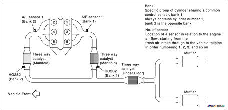
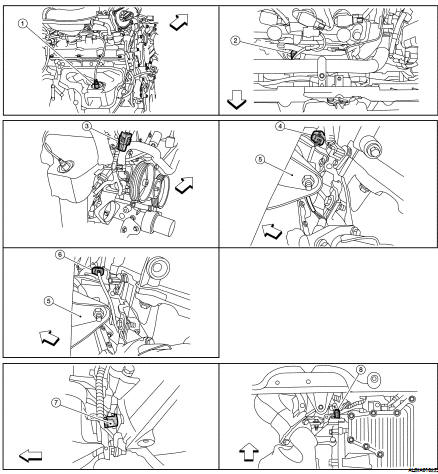
1. A/F sensor 1 (bank 1)
2. A/F sensor 1 (bank 2)
3. HO2S2 (bank 1) harness connector
4. HO2S2 (bank 2) harness connector (CVT models)
5. Front engine mount
6. HO2S2 (bank 2) harness connector (M/T models)
7. Crankshaft position sensor (POS) (M/T models)
8. Crankshaft position sensor (POS) (CVT models)
1. Electronic controlled engine mount control solenoid valve
2. EVAP control system pressure sensor
3. EVAP canister vent control valve
4. EVAP canister
5. Injector harness connector
6. Intake valve timing control solenoid valve (bank 1)
7. Intake valve timing control solenoid valve (bank 2)
1. Knock sensor (bank 2)
2. Knock sensor (bank 1)
3. PNP switch (CVT models)
4. PNP switch (M/T models)
5. Battery
6. IPDM E/R
7. ECM
8. Refrigerant pressure sensor (shown with front grill removed)
9. Accelerator pedal
1. ASCD brake switch
2. Stop lamp switch
3. Brake pedal
4. ASCD steering switch
5. ASCD clutch switch (M/T models)
6. Clutch pedal
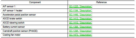
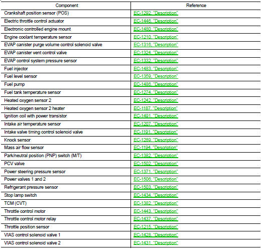
Component Description
 Function diagnosis
 Multiport fuel injection system