Nissan Altima (L32) 2007-2012 Service Manual: Engine speed signal circuit
Description
• ECM sends engine speed signal to power steering control unit.
Diagnosis Procedure
1.PERFORM ECM SELF-DIAGNOSIS

Perform ECM self-diagnosis.
Is any error system detected? YES >> Check the error system.
NO >> GO TO 2.
2.CHECK HARNESS BETWEEN ECM AND POWER STEERING CONTROL UNIT
1. Turn the ignition switch OFF.
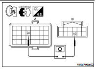
2. Disconnect ECM harness connector E10.
3. Disconnect power steering control unit harness connector.
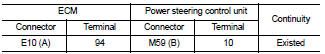
4. Check continuity between ECM harness connector E10 (A) terminal 94 and power steering control unit harness connector M59 (B) terminal 10.
Also check harness for short to ground and short to power.
Is the inspection result normal? YES >> GO TO 3.
NO >> Repair or replace damaged parts.
3.CHECK ENGINE SPEED SIGNAL (ECM SIDE)
1. Turn the ignition switch OFF.
2. Connect ECM harness connector.
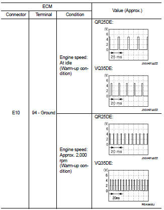
3. Check signal between ECM harness connector E10 terminal 94 and ground with oscilloscope.
Also check harness for short to ground and short to power.
Is the inspection result normal? YES >> GO TO 4.
NO >> Replace ECM. Refer to EC-34, "Component Parts Location" (QR25DE for California), EC-570, "Component Parts Location" (QR25DE except for California), EC-1058, "Component Parts Location" (VQ35DE).
4.CHECK ENGINE SPEED SIGNAL (POWER STEERING CONTROL UNIT SIDE)
1. Turn the ignition switch OFF.
2. Connect power steering control unit harness connector.
3. Check signal between power steering control unit harness connector M59 terminal 10 and ground with oscilloscope.
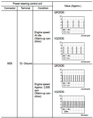
Also check harness for short to ground and short to power.
Is the inspection result normal? YES >> GO TO 5.
NO >> Replace power steering control unit.
5.CHECK TERMINALS AND HARNESS CONNECTORS
• Check power steering control unit pin terminals for damage or loose connection with harness connector.
• Check ECM pin terminals for damage or loose connection with harness connector.
Is the inspection result normal? YES >> Inspection End
NO >> Repair or replace damaged parts.
 Power steering solenoid valve
 Vehicle speed signal circuit