Nissan Altima (L32) 2007-2012 Service Manual: Front drive shaft
Removal and Installation (Left Side)
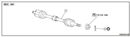
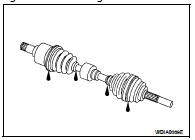
1. Drive shaft
2. Cotter pin
REMOVAL
1. Remove wheel and tire. Refer to WT-66, "Adjustment".
2. Remove wheel sensor from steering knuckle. Refer to BRC-63, "Removal and Installation" (ABS), BRC- 134, "Removal and Installation" (TCS/ABS), BRC-236, "Removal and Installation" (VDC/TCS/ABS).
3. Remove cotter pin. Then remove lock nut from drive shaft.
4. Remove brake hose lock plate. Then remove brake hose from strut.
5. Remove the lower ball joint pinch bolt using power tool, then separate lower ball joint from steering knuckle. Refer to FSU-12, "Exploded View".
6. Remove drive shaft from wheel hub and bearing assembly, using a puller or suitable tool. CAUTION: • When removing drive shaft, do not apply an excessive angle to drive shaft joint. Also be careful not to excessively extend slide joint.
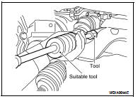
7. Remove the lefthand drive shaft from the transaxle.
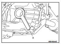
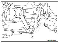
• Remove drive shaft from transaxle using Tool and drive shaft puller or suitable tool.
- Set Tool and a drive shaft puller or suitable tool between drive shaft (slide joint side) and transaxle as shown, then remove drive shaft.
Tool number : KV40107500 ( — )
INSPECTION AFTER REMOVAL
• Move joint up/down, left/right, and in axial direction. Check for any rough movement or significant looseness.
• Check boot for cracks or other damage, and for grease leakage.
• If damaged, disassemble drive shaft to verify damage, and repair or replace as necessary.
INSTALLATION
Installation is in the reverse order of removal. Note the following: CAUTION: Do not reuse non-reusable parts.
• In order to prevent damage to differential side oil seal, place Tool (A) onto oil seal before inserting drive shaft as shown. Slide drive shaft into slide joint and tap with a hammer to install securely.
Tool number : KV38106700 (J-34296)
• Install new circlip on drive shaft in the circular clip groove on transaxle side. Refer to FAX-15, "Disassembly and Assembly (Left Side)".
CAUTION: Make sure the new circlip on the drive shaft is securely fastened. • After its insertion, try to pull the flange out of the slide joint by hand.
If it pulls out, the circlip is not properly meshed with the transaxle side gear.
Removal and Installation (Right Side)
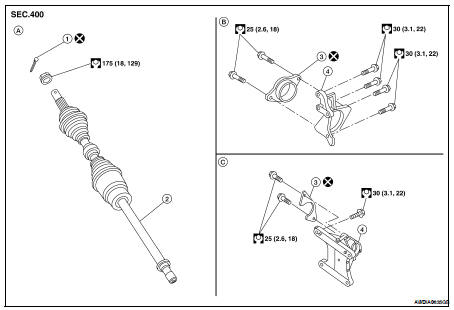
1. Cotter pin
2. Drive shaft
3. Retaining bracket
4. Support bearing bracket
A. Front RH drive shaft
B. QR25DE engine
C. VQ35DE engine
REMOVAL
1. Remove wheel and tire. Refer to WT-66, "Adjustment".
2. Remove wheel sensor from steering knuckle. Refer to BRC-63, "Removal and Installation" (ABS), BRC- 134, "Removal and Installation" (TCS/ABS), BRC-236, "Removal and Installation" (VDC/TCS/ABS).
3. Remove cotter pin. Then remove lock nut from drive shaft using power tool.
4. Remove brake hose lock plate. Then remove brake hose from strut.
5. Remove brake caliper using power tool, leaving hydraulic brake line attached. Hang caliper aside using wire. Refer to BR-30, "BRAKE CALIPER ASSEMBLY : Exploded View".
6. Remove front strut to steering knuckle bolts and nuts, then separate steering knuckle front strut. Refer to FSU-12, "Exploded View".
7. Remove drive shaft from wheel hub and bearing assembly, using a puller or suitable tool.
CAUTION: • When removing drive shaft, do not apply an excessive angle to drive shaft joint. Also be careful not to excessively extend slide joint.
8. Remove the retaining bracket bolts using power tool, and pry drive shaft from transaxle.
• Pry off drive shaft from transaxle.
INSPECTION AFTER REMOVAL
• Move joint up/down, left/right, and in axial direction. Check for any rough movement or significant looseness.
• Check boot for cracks or other damage, and for grease leakage.
• If damaged, disassemble drive shaft to verify damage, and repair or replace as necessary.
INSTALLATION
Installation is in the reverse order of removal. Note the following: CAUTION: Do not reuse non-reusable parts.
• In order to prevent damage to differential side oil seal, place Tool (A) onto oil seal before inserting drive shaft as shown. Slide drive shaft into slide joint and tap with a hammer to install securely.
Tool number : KV38106800 (J-34297)
• Install new circlip on drive shaft in the circular clip groove on transaxle side. Refer to FAX-15, "Disassembly and Assembly (Left Side)".
CAUTION: Make sure the new circlip on the drive shaft is securely fastened. • After its insertion, try to pull the flange out of the slide joint by hand.
If it pulls out, the circlip is not properly meshed with the transaxle side gear.
 Front wheel hub and knuckle
 Disassembly and assembly