Nissan Altima (L32) 2007-2012 Service Manual: Front wheel hub and knuckle
Removal and Installation
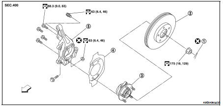
1. Cotter pin
2. Disc rotor
3. Wheel hub and bearing assembly
4. Splash guard
5. Steering knuckle

REMOVAL
1. Remove wheel and tire from vehicle. Refer to WT-66, "Adjustment".
2. Remove brake caliper using power tool, leaving brake caliper hydraulic lines connected. Reposition brake caliper aside with wire. Refer to BR-30, "BRAKE CALIPER ASSEMBLY : Exploded View".
NOTE: Avoid depressing brake pedal while brake caliper is removed.
3. Put alignment marks on disc rotor and wheel hub and bearing assembly, then remove disc rotor.
4. Remove wheel sensor from steering knuckle. Refer to BRC-63, "Removal and Installation" (ABS), BRC-134, "Removal and Installation" (TCS/ABS), BRC-236, "Removal and Installation" (VDC/TCS/ABS).
CAUTION: Do not pull on wheel sensor harness.
5. Remove cotter pin, then remove lock nut from drive shaft using power tool.
6. Remove steering outer tie-rod cotter pin at steering knuckle, then loosen nut using power tool. Refer to ST-17, "Removal and Installation".
7. Disconnect the outer tie-rod end from steering knuckle using Tool. Be careful not to damage ball joint boot.
CAUTION: To prevent damage to threads and to prevent Tool from coming off suddenly, temporarily tighten mounting nut.
Tool number : HT72520000 (J-25730-A)
8. Remove transverse link and steering knuckle pinch bolt and nut using power tool. Refer to FSU-12, "Exploded View".
9. Remove wheel hub and bearing assembly from drive shaft using a puller or suitable tool.
CAUTION: • When removing wheel hub and bearing assembly, do not apply an excessive angle to drive shaft joint. Also be careful not to excessively extend slide joint.
• Support drive shaft when removing.
10. Remove wheel hub and bearing assembly bolts using power tool.
11. Remove splash guard and wheel hub and bearing assembly from steering knuckle.
12. Remove the lower strut bolts and nuts using power tool. Refer to FSU-12, "Exploded View".
13. Remove steering knuckle from vehicle.
INSPECTION AFTER REMOVAL
Check for deformity, cracks and damage on each part, replace if necessary.
Ball Joint Inspection
• Check for boot breakage, axial looseness, and torque of transverse link ball joint and repair as necessary.
INSTALLATION
Installation is in the reverse order of removal.
CAUTION: Do not reuse non-reusable parts.
• When installing wheel hub and bearing assembly to steering knuckle, align cutout in toner ring cover with wheel sensor mounting hole in steering knuckle.
• When installing disc rotor on wheel hub and bearing assembly, align the marks.
(When not using the alignment mark, refer to BR-7, "DISC ROTOR : Inspection".)
 On-vehicle repair
 Front drive shaft