Nissan Altima 2007-2012 Service Manual: Front fog lamp

System Diagram

System Description

• BCM (Body Control Module) controls front fog lamp operation.

• IPDM E/R (Intelligent Power Distribution Module Engine Room) operates front fog lamp according to CAN communication signals from BCM.

• Combination meter operates front fog lamp indicator according to inputs via the CAN communication lines.

Component Parts Location

1. IPDM E/R E17, E18, E200

2. BCM M16, M17, M18, M19 (view with instrument panel removed)

3. Combination switch M28

Component Description

FRONT FOG LAMP OPERATION

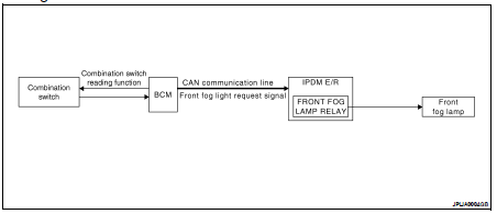
When the lighting switch is in front fog lamp ON position and also in 1ST or 2ND position or AUTO position (headlamp is ON), the BCM detects FR FOG ON and the HEAD LAMP1, 2 ON or the AUTO LIGHT ON. The BCM sends a front fog lamp request ON signal through the CAN communication lines to the IPDM E/R. The IPDM E/R then turns ON the front fog lamp relay sending power to the front fog lamps.

The combination meter also receives a front fog lamp request ON signal through the CAN communication lines at which time it turns the front fog indicator ON.

    Auto light system
    System Diagram System Description • BCM (Body Control Module) controls auto light operation according to signals from optical sensor, lighting switch and ignition switch. • IPDM E/R (I ...

    Turn signal and hazard warning lamps
    System Diagram System Description • BCM (Body Control Module) controls turn signal lamp (RH and LH) and hazard warning lamp operation. • Combination meter operates turn (RH and LH) indic ...

    Other materials:

    Main line between dlc and abs circuit
    Diagnosis Procedure INSPECTION PROCEDURE 1.CHECK CONNECTOR 1. Turn the ignition switch OFF. 2. Disconnect the battery cable from the negative terminal. 3. Check the following terminals and connectors for damage, bend and loose connection (connector side and harness side). - Harness co ...

    Fender protector
    Removal and Installation 1. Fender protector 2. Fender protector side cover A. J-clips B. Clips C. Center mudguard screw a. Sheet metal nut REMOVAL 1. Remove the engine under cover. Refer to EXT-34, "Removal and Installation". 2. Remove the screw from center mudguard. 3 ...

    P0101 maf sensor
    Description The mass air flow sensor (1) is placed in the stream of intake air. It measures the intake flow rate by measuring a part of the entire intake flow. The mass air flow sensor controls the temperature of the hot wire to a certain amount. The heat generated by the hot wire is reduced a ...