Nissan Altima (L32) 2007-2012 Service Manual: Turn signal and hazard warning lamps
System Diagram
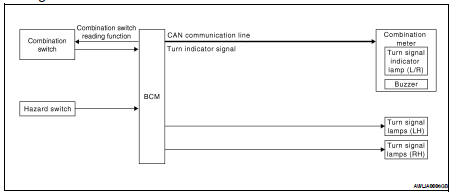
System Description
• BCM (Body Control Module) controls turn signal lamp (RH and LH) and hazard warning lamp operation.
• Combination meter operates turn (RH and LH) indicator according to CAN communication signals from BCM.
Component Parts Location
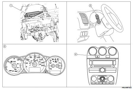
1. BCM M16, M17, M18, M19 (view with instrument panel removed)
2. Combination switch M28
3. Combination meter M24
4. Hazard switch M54
Component Description
TURN SIGNAL OPERATION
When the turn signal switch is in LH or RH position with the ignition switch in ON position, the BCM detects the TURN RH or TURN LH ON request. The BCM outputs the flasher output signal to the respective turn signal lamp. The BCM sends a turn indicator signal ON request through the CAN communication lines to the combination meter. The combination meter then activates the appropriate turn signal indicator and audible buzzer.
HAZARD LAMP OPERATION
When the hazard switch is in ON position, the BCM detects the hazard switch signal ON. The BCM outputs the flasher output signal (right and left). The BCM sends a hazard indicator signal ON request through the CAN communication lines to the combination meter. The combination meter then activates the hazard indicator and audible buzzer.
REMOTE KEYLESS ENTRY OPERATION
The remote keyless entry receiver transmits Intelligent Key signal to BCM, then BCM controls hazard lamps.
Refer to SEC-26, "System Description".
 Front fog lamp
 Parking, license plate and tail
lamps
Parking, license plate and tail
lamps