Nissan Altima (L32) 2007-2012 Service Manual: Front seat
Exploded View
DRIVER'S SEAT
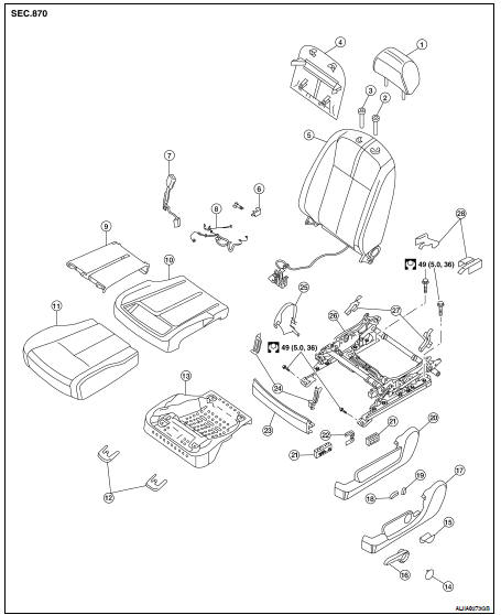
1. Headrest
2. Headrest holder (locked)
3. Headrest holder (free)
4. Seatback board
5. Seatback assembly
6. Slide cover
7. Seat belt buckle
8. Seat harness
9. Seat cushion heater unit
10. Seat cushion
11. Seat trim
12. Front leg covers
13. Seat cushion frame
14. Manual seat lifter lever finisher
15. Manual seat recliner handle
16. Manual seat lifter lever
17. Manual seat outer finisher
18. Seat slide switch
19. Seat reclining switch
20. Power seat outer finisher
21. Seat switch assembly
22. LH seat bracket
23. Front seat finisher
24. Cushion bracket
25. Inner seat cover
26. Seat frame assembly
27. Cushion finishers
28. Rear leg covers
PASSENGER'S SEAT
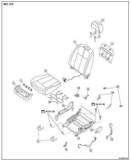
1. Headrest
2. Headrest holder (locked)
3. Headrest holder (free)
4. Seatback board
5. Seatback assembly
6. Seat cushion assembly
7. Bushing
8. Seat cushion frame assembly
9. Front leg covers
10. Cushion bracket
11. Seat frame assembly
12. Seat harness
13. Seat belt buckle
14. Inner finisher
15. Outer finisher
16. Seat cushion supporter
17. Recliner mechanism
18. Finisher
19. Cushion finishers
20. Rear leg covers
Removal and Installation
REMOVAL
CAUTION: • Before removing the front seat, turn the ignition switch off, disconnect both battery terminals and wait and least 3 minutes.
• When checking the power seat circuit for continuity using a circuit tester, do not confuse its connector with the side air bag module connector. Such an error may cause the air bag to deploy.
• Do not drop, tilt, or bump the side air bag module while installing the seat. Always handle it with care.
• After front side air bag module inflates, front seatback assembly must be replaced.
• Always replace passenger seat cushion as an assembly with Occupant Classification System.
• When removing or installing the seat trim, handle it carefully to keep dirt out and avoid damage.
• When removing and installing, use shop cloths to protect the parts from damage where they may interfere with other parts.
1. Slide the seat until the four seat bolts are visible and a tool can be inserted.
2. Disconnect the negative and positive battery terminals and wait at least 3 minutes.
3. Disconnect the harness connector for the side air bag module.
4. Disconnect the power seat harness connector and vehicle harness clip from the vehicle.
5. Remove the seat leg covers.
6. Remove the four seat bolts.
INSTALLATION
Installation is in the reverse order of removal.
• When installing the LH front seats tighten the bolts as shown.
• When installing the RH front seats tighten the bolts as shown.
 On-vehicle repair
 Rear seat