Nissan Altima (L32) 2007-2012 Service Manual: Front wiper auto stop signal circuit
Component Function Check
1. CHECK FRONT WIPER (AUTO STOP) OPERATION
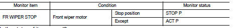
1. Select "FRONT WIPER STOP" of IPDM E/R DATA MONITOR item.
2. Operate the front wiper.
3. With the front wiper operation, check the monitor status.
Is the status of item normal?
YES >> Auto stop signal circuit is normal.
NO >> Refer to WW-24, "Diagnosis Procedure".
Diagnosis Procedure
1. CHECK FRONT WIPER MOTOR (AUTO STOP) OUTPUT VOLTAGE
1. Turn the ignition switch OFF.
2. Disconnect front wiper motor.
3. Turn the ignition switch ON.
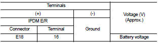
4. Check voltage between IPDM E/R harness connector and
ground.
Is the measurement normal?
YES >> GO TO 2
NO >> Replace IPDM E/R. Refer to PCS-48, "Removal and Installation".
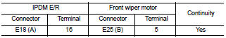
2. CHECK FRONT WIPER MOTOR (AUTO STOP) CIRCUIT CONTINUITY
1. Turn the ignition switch OFF.
2. Disconnect IPDM E/R.
3. Check continuity between IPDM E/R harness connector (A) and
front wiper motor harness connector (B).
Does continuity exist?
YES >> GO TO 3
NO >> Repair or replace harness.
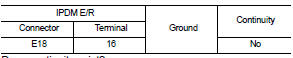
3. CHECK FRONT WIPER MOTOR (AUTO STOP) SHORT CIRCUIT
Check continuity between IPDM E/R harness connector and ground.
Does continuity exist?
YES >> Repair or replace harness.
NO >> Replace front wiper motor. Refer to WW-116, "FRONT
WIPER DRIVE ASSEMBLY : Removal and Installation".
Component Function Check
1. CHECK FRONT WIPER HI OPERATION
1. Start IPDM E/R auto active test. Refer to PCS-14, "Diagnosis Description".
2. Check that the front wiper operates at the ...
Diagnosis Procedure
1.CHECK FRONT WIPER MOTOR (GND) OPEN CIRCUIT
1. Turn the ignition switch OFF.
2. Disconnect front wiper motor.
3. Check continuity between front wiper motor harness connec ...
Other materials: NISSAN Vehicle Immobilizer System
The NISSAN Vehicle Immobilizer System
will not allow the engine to start without
the use of a registered key.
If the engine fails to start using a registered
key (for example, when interference is
caused by another registered key, an automated
toll road device or automatic payment
device on the key ...
Trip computer
1. Home
This display indicates the home screen.
2. Vehicle speed
The vehicle speed mode shows the current
vehicle speed and the average vehicle
speed since the last reset.
Average vehicle speed:
Press and hold the OK button on the steering
wheel to bring up the drive computer Reset
menu, and follow ...
USB/iPod charging ports (if so equipped)
Front (Type A) (if so equipped)
Front (Type B) (if so equipped)
Front (Type C) (if so equipped)
Rear (if so equipped)
Type-C USB
Type-A USB
There are USB charging ports located in
the rear seat area on the back of the center
console. These ports will charge compatible
devices.
NOTE:
Not al ...

 Front wiper motor hi circuit
 Front wiper motor ground circuit