Nissan Altima (L32) 2007-2012 Service Manual: Front wiper drive assembly
Removal and Installation
REMOVAL
1. Operate front wiper motor, and stop at the auto stop position.
2. Remove wiper arms. Refer to WW-116, "FRONT WIPER ARMS : Removal and Installation".
3. Remove the cowl top cover. For Sedan Refer to EXT-39, "Removal and Installation". For Coupe Refer to EXT-18, "Removal and Installation".
4. Remove the strut brace bolts (A), detach the wiper drive assembly harness clips, then remove the strut brace (1).
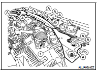
5. Detach the wiper drive harness clip from the wiper drive assembly frame.
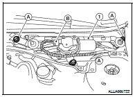
6. Remove the front wiper drive assembly bolts (A), disconnect the wiper drive motor connector (B) and remove the front wiper drive assembly (1).
INSTALLATION
1. Install the front wiper drive assembly.
2. Connect wiper motor connector. Turn wiper switch ON to operate wiper motor, then turn wiper switch OFF (auto stop).
3. Attach the wiper drive harness clip to the wiper drive assembly frame.
4. Install the strut brace, then attach the wiper drive assembly harness clips.
5. Install the cowl top cover. For Sedan Refer to EXT-39, "Removal and Installation". For Coupe Refer to EXT-18, "Removal and Installation" 6. Attach the wiper arms. Refer to WW-116, "FRONT WIPER ARMS : Removal and Installation".
7. Adjustment of wiper arm stop location. Refer to WW-116, "FRONT WIPER ARMS : Removal and Installation".
 Front wiper ARMS
 Front washer