Nissan Altima (L32) 2007-2012 Service Manual: Fuel pump
Description
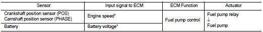
*: ECM determines the start signal status by the signals of engine speed and battery voltage.
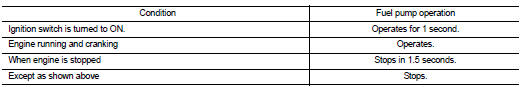
The ECM activates the fuel pump for several seconds after the ignition switch is turned ON to improve engine start ability. If the ECM receives a engine speed signal from the camshaft position sensor (PHASE), it knows that the engine is rotating, and causes the pump to operate. If the engine speed signal is not received when the ignition switch is ON, the engine stalls. The ECM stops pump operation and prevents battery discharging, thereby improving safety. The ECM does not directly drive the fuel pump. It controls the ON/OFF fuel pump relay, which in turn controls the fuel pump.
Component Function Check
1.CHECK FUEL PUMP FUNCTION
1. Turn ignition switch ON.
2. Pinch fuel feed hose (2) with two fingers.
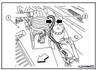
Fuel pressure pulsation should be felt on the fuel feed hose for 1 second after ignition switch is turned ON.
Is the inspection result normal? YES >> INSPECTION END
NO >> EC-959, "Diagnosis Procedure".
Diagnosis Procedure
1.CHECK FUEL PUMP POWER SUPPLY CIRCUIT-I
1. Turn ignition switch OFF.
2. Disconnect ECM harness connector.
3. Turn ignition switch ON.
4. Check the voltage between ECM harness connector and ground.
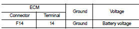
Is the inspection result normal? YES >> GO TO 4.
NO >> GO TO 2.
2.CHECK FUEL PUMP POWER SUPPLY CIRCUIT-II
1. Turn ignition switch OFF.
2. Disconnect IDPDM E/R harness connector F10.
3. Check the continuity between IPDM E/R harness connector and ECM harness connector.
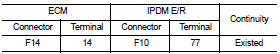
Is the inspection result normal? YES >> GO TO 3.
NO >> Repair open circuit or short to ground or short to power in harness or connectors.
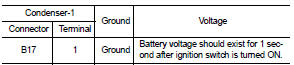
3.CHECK CONDENSER-1 POWER SUPPLY CIRCUIT-I
1. Reconnect all harness connectors disconnected.
2. Disconnect condenser-1 harness connector.
3. Turn ignition switch ON.
4. Check the voltage between condenser-1 harness connector and ground.
Is the inspection result normal? YES >> GO TO 5.
NO >> GO TO 4.
4.CHECK 15A FUSE
1. Turn ignition switch OFF.
2. Disconnect 15A fuse (No. 32) from IPDM E/R.
3. Check 15A fuse.
Is the inspection result normal? YES >> GO TO 6.
NO >> Replace fuse.
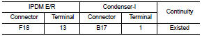
5.CHECK CONDENSER-1 POWER SUPPLY CIRCUIT-II
1. Disconnect IPDM E/R harness connector E18.
2. Check the continuity between IPDM E/R harness connector and condenser-1 harness connector.
3. Also check harness for short to ground and short to power.
Is the inspection result normal? YES >> GO TO 13.
NO >> GO TO 7.
6.DETECT MALFUNCTIONING PART
Check the following.
• Harness connectors E29, B10
• IPDM E/R connector F10
• Harness for open or short between IPDM E/R and condenser-I
>> Repair open circuit or short to power in harness or connectors.
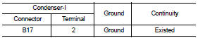
7.CHECK CONDENSER GROUND CIRCUIT
1. Turn ignition switch OFF.
2. Disconnect dropping resistor harness connector.
3. Check the continuity between condenser-I harness connector and ground.
4. Also check harness for short to ground and short to power.
Is the inspection result normal? YES >> GO TO 8.
NO >> Repair open circuit or short to power in harness or connectors.
8.CHECK CONDENSER-1
Refer to EC-962, "Component Inspection (Condenser-1)".
Is the inspection result normal? YES >> GO TO 9.
NO >> Replace condenser-1.
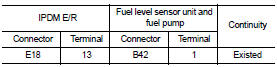
9.CHECK FUEL PUMP POWER SUPPLY CIRCUIT-III
1. Disconnect “fuel level sensor unit and fuel pump” harness connector.
2. Check the continuity between IPDM E/R harness connector and “fuel level sensor unit and fuel pump” and ground.
Is the inspection result normal? YES >> GO TO 11.
NO >> GO TO 10.
10.DETECT MALFUNCTIONING PART
Check the following.
• Harness connector E29, B10
• Harness for open or short between “fuel level sensor unit and fuel pump” and IPDM E/R
• Harness for open or short between “fuel level sensor unit and fuel pump” and ground
>> Repair open circuit or short to power in harness or connectors.
11.CHECK FUEL PUMP GROUND CIRCUIT
1. Check the continuity between “fuel level sensor unit and fuel pump” and ground.
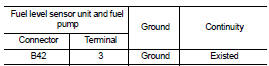
2. Also heck harness for short to power.
Is the inspection result normal? YES >> GO TO 12.
NO >> Repair open circuit or short to power in harness or connectors.
12.CHECK FUEL PUMP
Refer to EC-962, "Component Inspection (Fuel Pump)".
Is the inspection result normal? YES >> GO TO 13.
NO >> Replace fuel pump.
13.CHECK INTERMITTENT INCIDENT
Refer to GI-42, "Intermittent Incident".
Is the inspection result normal? YES >> Replace IPDM E/R.
NO >> Repair or replace harness or connectors.
Component Inspection (Fuel Pump)
1.CHECK FUEL PUMP
1. Turn ignition switch OFF.
2. Disconnect “fuel level sensor unit and fuel pump” harness connector.
3. Check resistance between “fuel level sensor unit and fuel pump” terminals as follows.
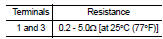
Is the inspection result normal? YES >> INSPECTION END
NO >> Replace “fuel level sensor unit and fuel pump”.
Component Inspection (Condenser-1)
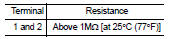
1.CHECK CONDENSER
1. Turn ignition switch OFF.
2. Disconnect condenser-1 harness connector.
3. Check resistance between condenser-1 terminals as follows.
Is the inspection result normal? YES >> INSPECTION END
NO >> Replace condenser-1.
 Fuel injector
 Ignition signal