Nissan Altima (L32) 2007-2012 Service Manual: Headlamp (HI) circuit
Description
The IPDM E/R (intelligent power distribution module engine room) controls the headlamp high relay based on inputs from the BCM over the CAN communication lines. When the headlamp high relay is energized, power flows through fuses 48 and 49, located in the IPDM E/R. Power then flows to the front combination lamps to the headlamp high beam.
Component Function Check
1.CHECK HEADLAMP (HI) OPERATION

1. Start IPDM E/R auto active test. Refer to PCS-14, "Diagnosis Description".
2. Check that the headlamp switches to the high beam.
NOTE: HI/LO is repeated 1 second each when using the IPDM E/R auto active test.

1. Select "EXTERNAL LAMP" of IPDM E/R active test item.
2. With operating the test items, check that the headlamp switches to the high beam.

Does the headlamp switch to the high beam? YES >> Headlamp (HI) circuit is normal.
NO >> Refer to EXL-40, "Diagnosis Procedure".
Diagnosis Procedure
1.CHECK HEADLAMP (HI) FUSES
1. Turn the ignition switch OFF.
2. Check that the following fuses are not open.
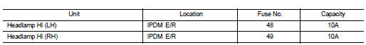
Is the fuse open? YES >> Repair the harness and replace the fuse.
NO >> GO TO 2
2.CHECK HEADLAMP (HI) OUTPUT VOLTAGE

1. Turn the ignition switch OFF.
2. Disconnect the front combination lamp connector.
3. Turn the ignition switch ON.
4. Select "EXTERNAL LAMP" of IPDM E/R active test item.
5. With EXTERNAL LAMP ON, check the voltage between the combination lamp connector and ground.
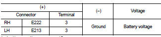
Is battery voltage present? YES >> GO TO 4
NO >> GO TO 3
3.CHECK HEADLAMP (HI) CIRCUIT FOR OPEN
1. Turn the ignition switch OFF.
2. Disconnect IPDM E/R connector.
3. Check continuity between the IPDM E/R harness connector and the front combination lamp harness connector.
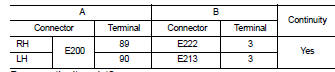
Does continuity exist? YES >> GO TO 4
NO >> Repair the harnesses or connectors.
4.CHECK FRONT COMBINATION LAMP (HI) GROUND CIRCUIT
1. Disconnect the front combination lamp connector.
2. Check continuity between the front combination lamp harness connector terminal and ground.
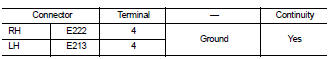
Does continuity exist? YES >> Inspect the headlamp bulb.
NO >> Repair the harness.
 IPDM E/R (Intelligent power distribution
module engine room)
IPDM E/R (Intelligent power distribution
module engine room) Headlamp (LO) circuit