Nissan Altima (L32) 2007-2012 Service Manual: Headlamp (xenon type)
System Diagram
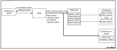
System Description
Control of the headlamp system is dependent upon the position of the lighting switch (combination switch).
When the lighting switch is placed in the 2nd position, the BCM (body control module) receives input requesting the headlamps and park lamps to illuminate. This input is communicated to the IPDM E/R (intelligent power distribution module engine room) across the CAN communication lines. The CPU (central processing unit) of the IPDM E/R controls the headlamp high and headlamp low relay coils. When energized, these relays direct power to the respective headlamps, which then illuminate.
Component Parts Location
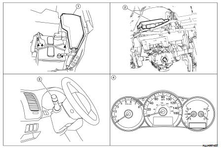
1. IPDM E/R E17, E18, E200
2. BCM M16, M17, M18, M19 (view with instrument panel removed)
3. Combination Switch M28
4. Combination Meter M24
Component Description
XENON HEADLAMP
A Xenon type headlamp is adapted to the low beam headlamps. Xenon bulbs do not use a filament. Instead, they produce light when a high voltage current is passed between two tungsten electrodes through a mixture of xenon (an inert gas) and certain other metal halides. In addition to added lighting power, electronic control of the power supply gives the headlamps stable quality and tone color.
Following are some of the many advantages of the xenon type headlamp.
• The light produced by the headlamps is a white color comparable to sunlight that is easy on the eyes.
• Light output is nearly double that of halogen headlamps, affording increased area of illumination.
• The light features a high relative spectral distribution at wavelengths to which the human eye is most sensitive.
This means that even in the rain, more light is reflected back from the road surface toward the vehicle, for added visibility.
• Power consumption is approximately 25 percent less than halogen headlamps, reducing battery load.
HIGH BEAM OPERATION/FLASH-TO-PASS OPERATION
With the lighting switch in the 2ND position and placed in HIGH position, the BCM receives input requesting the headlamp high beams to illuminate. The flash to pass feature can be used any time and also sends a signal to the BCM. This input is communicated to the IPDM E/R across the CAN communication lines. The CPU of the combination meter controls the ON/OFF status off the HIGH BEAM indicator. The CPU of the IPDM E/ R controls the headlamp high relay coil which directs power to the high beam headlamps.
EXTERIOR LAMP BATTERY SAVER CONTROL
With the lighting switch (combination switch) in the 2nd position and the ignition switch is turned from ON or ACC to OFF, the battery saver feature is activated.
Under this condition, the headlamps remain illuminated for 5 minutes unless the lighting switch position is changed. If the lighting switch position is changed, then the headlamps are turned off.
This setting can be changed by CONSULT-III. Refer to EXL-30, "BATTERY SAVER : CONSULT-III Function".
 Function diagnosis
 Headlamp (halogen type)