Nissan Altima (L32) 2007-2012 Service Manual: Headlamp (halogen type)
System Diagram
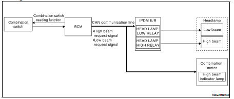
System Description
Control of the headlamp system operation is dependent upon the position of the lighting switch (combination switch). When the lighting switch is placed in the 2nd position, the BCM (body control module) receives input requesting the headlamps and park lamps to illuminate. This input is communicated to the IPDM E/R (intelligent power distribution module engine room) across the CAN communication lines. The CPU (central processing unit) of the IPDM E/R controls the headlamp high and headlamp low relay coils. When energized, these relays direct power to the respective headlamps, which then illuminate.
Component Parts Location
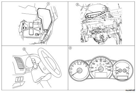
1. IPDM E/R E17, E18, E200
2. BCM M16, M17, M18, M19 (view with instrument panel removed)
3. Combination switch M28
4. Combination meter M24
Component Description
LOW BEAM OPERATION
When the lighting switch is in 2ND position, the BCM receives input requesting the headlamps to illuminate.
This input is communicated to the IPDM E/R across the CAN communication lines. The CPU of the IPDM E/R controls the headlamp low relay coil which supplies power to the low beam headlamps.
HIGH BEAM OPERATION/FLASH-TO-PASS OPERATION
With the lighting switch in the 2ND position and placed in HIGH position, the BCM receives input requesting the headlamp high beams to illuminate. The flash to pass feature can be used any time and also sends a signal to the BCM. This input is communicated to the IPDM E/R across the CAN communication lines. The CPU of the combination meter controls the ON/OFF status off the HIGH BEAM indicator. The CPU of the IPDM E/R controls the headlamp high relay coil which supplies power to the high beam headlamps.
The combination meter receives a high beam request signal (ON) through the CAN communication lines and turns the high beam indicator lamp ON.
EXTERIOR LAMP BATTERY SAVER CONTROL
With the lighting switch (combination switch) in the 2nd position and the ignition switch is turned from ON or ACC to OFF, the battery saver feature is activated.
Under this condition, the headlamps remain illuminated for 5 minutes unless the lighting switch position is changed. If the lighting switch position is changed, then the headlamps are turned off.
This setting can be changed by CONSULT-III. Refer to EXL-30, "BATTERY SAVER : CONSULT-III Function".
 Headlamp (xenon type)
 Daytime running light system