Nissan Altima (L33) 2013-2018 Owners Manual: Heater and Air Conditioner (automatic) (if so equipped)
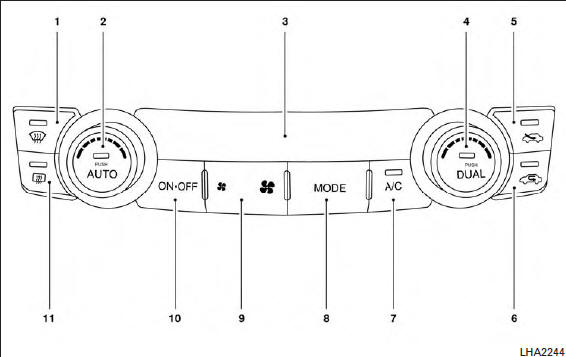
1.  (front defroster) button
2. Temperature control dial (driver’s side)/
AUTO (automatic) climate control button
3. Display screen
4. Temperature control dial (passenger’s
side)/DUAL (passenger’s side temperature
control) button
5.  Fresh air intake button
6.  Air recirculation button
7. A/C (air conditioner) button
8. MODE (manual air flow control) button
9.  (fan speed control) buttons
10. ON-OFF button
11.  (rear window defroster) button
WARNING
● The air conditioner cooling function operates only when the engine is running.
● Do not leave children or adults who would normally require the assistance of others alone in your vehicle. Pets should also not be left alone. They could accidentally injure themselves or others through inadvertent operation of the vehicle. Also, on hot, sunny days, temperatures in a closed vehicle could quickly become high enough to cause severe or possibly fatal injuries to people or animals.
● Do not use the recirculation mode for long periods as it may cause the interior air to become stale and the windows to fog up.
Start the engine and operate the controls to activate the air conditioner.
NOTE:
● Odors from inside and outside the vehicle can build up in the air conditioner unit. Odor can enter the passenger compartment through the vents.
● When parking, set the heater and air conditioner controls to turn off air recirculation to allow fresh air into the passenger compartment.
This should help reduce odors inside the vehicle.
 Air flow charts
 Automatic operation