Nissan Altima (L32) 2007-2012 Service Manual: Ignition coil
Exploded View
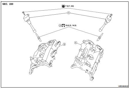
1. Ignition coil
2. Spark plug
3. Rocker cover (RH)
4. Rocker cover (LH)
Removal and Installation LH
REMOVAL
1. Remove engine room cover.
2. Disconnect ignition coil connector.
3. Remove the ignition coil.
CAUTION:
Never shock ignition coil.
INSTALLATION
Installation is in the reverse order of removal.
Removal and Installation RH
REMOVAL
1. Remove the intake manifold collector. Refer to EM-130, "Removal and
Installation".
2. Disconnect ignition coil connector.
3. Remove the ignition coil.
CAUTION:
Never shock ignition coil.
INSTALLATION
Installation is in the reverse order of removal.
Removal and Installation
1. Oil pan baffle
2. O-ring
3. Gasket
4. Oil pressure switch
5. Oil cooler gasket
6. Oil cooler
7. Oil cooler connection
8. Oil filter
9. Lower oil pan
10. Oil str ...
Removal and Installation
1. Fuel feed hose
2. Quick connector cap
3. Fuel tube
4. O-ring
5. Fuel damper
6. Fuel damper cap
7. Clip
8. O-ring (black)
9. Fuel injector
10. O-ring (green)
A. ...
 Oil pan and oil strainer
 Fuel injector and fuel tube