Nissan Altima (L32) 2007-2012 Service Manual: In-vehicle sensor
Component Description
In-vehicle sensor
The in-vehicle sensor (1) is located on instrument lower panel LH. It converts variations in temperature of compartment air drawn from the aspirator into a resistance value. It is then input into the front air control.
Aspirator
The aspirator (1) is located on LH side of heater and cooling unit. It produces vacuum pressure due to air discharged from the heater and cooling unit, continuously taking compartment air in the aspirator.
Diagnosis Procedure
DIAGNOSTIC PROCEDURE
SYMPTOM: In-vehicle sensor circuit is open or shorted.
1.CHECK VOLTAGE BETWEEN IN-VEHICLE SENSOR HARNESS CONNECTOR AND BODY GROUND
1. Disconnect in-vehicle sensor connector M34.
2. Press ignition switch ON.
3. Check voltage between in-vehicle sensor harness connector M34 terminal 1 and ground.
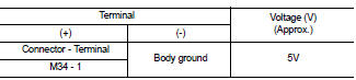
Is the inspection result normal? YES >> GO TO 2
NO >> GO TO 4
2.CHECK IN-VEHICLE SENSOR GROUND CIRCUIT BETWEEN IN-VEHICLE SENSOR AND FRONT AIR CONTROL
1. Press ignition switch OFF.
2. Disconnect front air control connector M37.
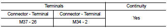
3. Check continuity between front air control harness connector M37 (A) terminal 26 and in-vehicle sensor harness connector M34 (B) terminal 2.
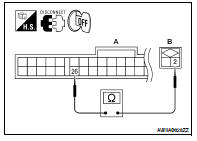
If OK, check harness for short.
Is the inspection result normal? YES >> GO TO 3
NO >> Repair harness or connector.
3.CHECK IN-VEHICLE SENSOR
Check in-vehicle sensor. Refer to HAC-55, "Component Inspection".
Is the inspection result normal? YES >> 1. Replace front air control. Refer to VTL-8, "Removal and Installation".
2. Confirm system operation.
NO >> 1. Replace in-vehicle sensor. Refer to VTL-9, "Removal and Installation".
2. Confirm system operation.
4.CHECK IN-VEHICLE SENSOR CIRCUIT BETWEEN AMBIENT SENSOR AND FRONT AIR CONTROL
1. Press ignition switch OFF.
2. Disconnect front air control connector M37.
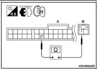
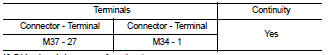
3. Check continuity between front air control harness connector M37 (A) terminal 27 and in-vehicle sensor harness connector M34 (B) terminal 1.
If OK, check harness for short.
Is the inspection result normal? YES >> 1. Replace front air control. Refer to VTL-8, "Removal and Installation".
2. Confirm system operation.
NO >> Repair harness or connector.
Component Inspection
In-vehicle Sensor
After disconnecting in-vehicle sensor connector M34, measure resistance between terminals 1 and 2 at sensor side, using the table below.
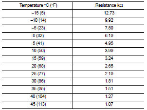
If NG, replace in-vehicle sensor. Refer to VTL-9, "Removal and Installation".
 Ambient sensor
 Sunload sensor