Nissan Altima (L32) 2007-2012 Service Manual: Sunload sensor
Description
COMPONENT DESCRIPTION
The sunload sensor (1) is located on the LH tweeter grille. It detects sunload entering through windshield by means of a photo diode. The sensor converts the sunload into a current value which is then input into the front air control.
SUNLOAD INPUT PROCESS
The front air control also includes a processing circuit which averages the variations in detected sunload over a period of time. This prevents drastic swings in the automatic temperature control system operation due to small or quick variations in detected sunload.
For example, consider driving along a road bordered by an occasional group of large trees. The sunload detected by the sunload sensor will vary whenever the trees obstruct the sunlight. The processing circuit averages the detected sunload over a period of time, so that the (insignificant) effect of the trees momentarily obstructing the sunlight does not cause any change in the automatic temperature control system operation.
On the other hand, shortly after entering a long tunnel, the system will recognize the change in sunload, and the system will react accordingly.
Diagnosis Procedure
DIAGNOSTIC PROCEDURE
SYMPTOM: Sunload sensor circuit is open or shorted.
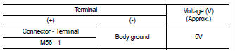
1.CHECK VOLTAGE BETWEEN SUNLOAD SENSOR HARNESS CONNECTOR AND BODY GROUND
1. Disconnect sunload sensor connector.
2. Press ignition switch ON.
3. Check voltage between sunload sensor harness connector M56 terminal 1 and ground.
Is the inspection result normal? YES >> GO TO 2
NO >> GO TO 4
2.CHECK SUNLOAD SENSOR GROUND CIRCUIT BETWEEN SUNLOAD SENSOR AND FRONT AIR CONTROL
1. Press ignition switch OFF.
2. Disconnect front air control connector M37.
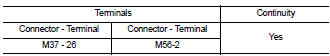
3. Check continuity between front air control connector M37 (A) terminal 26 and sunload sensor harness connector M56 (B) terminal 2.
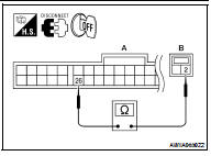
If OK, check harness for short.
Is the inspection result normal? YES >> GO TO 3
NO >> Repair harness or connector.
3.CHECK SUNLOAD SENSOR
Check sunload sensor. Refer to HAC-57, "Component Inspection".
Is the inspection result normal? YES >> 1. Replace front air control. Refer to VTL-8, "Removal and Installation".
2. Confirm system operation.
NO >> 1. Replace sunload sensor. Refer to VTL-10, "Removal and Installation".
2. Confirm system operation.
4.CHECK SUNLOAD SENSOR CIRCUIT BETWEEN SUNLOAD SENSOR AND FRONT AIR CONTROL
1. Press ignition switch OFF.
2. Disconnect front air control connector M37.
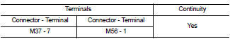
3. Check continuity between front air control connector M37 (A) terminal 7 and sunload sensor harness connector M56 (B) terminal 1.
If OK, check harness for short.
Is the inspection result normal? YES >> 1. Replace front air control. Refer to VTL-8, "Removal and Installation".
2. Confirm system operation.
NO >> Repair harness or connector.
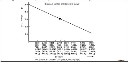
Component Inspection
Sunload Sensor
Measure voltage between front air control harness connector M37 terminal 7 and ground.
If NG, replace front air control. Refer to VTL-8, "Removal and Installation".
• When checking sunload sensor, select a place where sun shines directly on it.
 In-vehicle sensor
 Intake sensor