Nissan Altima (L32) 2007-2012 Service Manual: Inspection and adjustment
ADDITIONAL SERVICE WHEN REPLACING CONTROL UNIT
Precaution for TCM and CVT Assembly Replacement
CAUTION: • Check if new data (Unit ID) are entered correctly after replacing CVT assembly and erasing data in TCM. (Connect CONSULT-III, and then turn ignition switch OFF.) • When replacing CVT assembly or TCM, refer to the pattern table below and erase the EEPROM in the TCM if necessary.
EEPROM ERASING PATTERNS
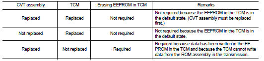
METHOD FOR ERASING THE EEPROM IN THE TCM
1. Turn ignition switch ON.
2. Move selector lever to “R” position.
3. Perform “SELF-DIAG RESULTS” mode for “TRANSMISSION”.
4. Press the brake pedal and turn the brake switch ON.
5. Press the accelerator pedal (0.5/8 - 4/8 throttle) not to exceed the half, and hold it in the half or less open position. (This will set the closed throttle position signal to OFF and the wide open throttle position signal to OFF.) 6. Perform “ERASE”.
7. Wait 3 seconds and then release the accelerator pedal.
8. Turn ignition switch OFF.
METHOD FOR WRITING DATA FROM THE ROM ASSEMBLY IN THE TRANSAXLE
In the following procedure, the TCM reads data from the ROM assembly and writes it to the EEPROM in the TCM.
1. Erase the EEPROM in the TCM.
2. Move selector lever to “P” position.
3. Turn ignition switch ON.
CHECK METHOD
• Standard: About 2 seconds after the ignition switch ON, the CVT indicator lamp lights up for 2 seconds.
• Non-standard: Even after the ignition switch ON, the CVT indicator lamp does not light up after 2 seconds or illuminates immediately.
CAUTION: Perform in the “P” or “N” position.
Action for Non-standard
• Replace the CVT assembly.
• Replace the TCM.
 Diagnosis and repair workflow
 Function diagnosis