Nissan Altima (L32) 2007-2012 Service Manual: Interior room lamp
Removal and Installation
FRONT ROOM/MAP LAMP
NOTE: For non-sunroof equipped vehicles, the front room/map lamp assembly is an integral part of the headinlining and repaired only as an assembly. Refer to INT-20, "Removal and Installation" for coupe models, and INT-42, "Removal and Installation" for sedan models.
Removal (Sunroof Equipped Vehicles) 1. Disconnect the negative battery terminal.
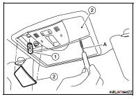
2. Release the metal clips and drop front edge of front room/map lamp (1) away from headlining. Slide front room/map lamp forward in vehicle to clear pawls at rear.


3. Disconnect the connectors, then remove front room/map lamp.
Installation (Sunroof Equipped Vehicles)
Installation is in the reverse order of removal.
Bulb Replacement
1. Disconnect the negative battery terminal.
2. Using a suitable tool (A), remove front room/map lamp lens (2) RH/LH.
3. Pull bulb (1) straight out to remove.

VANITY MIRROR LAMP
Removal
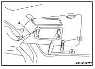
The vanity mirror lamp is replaced as part of the sunvisor assembly. Refer to INT-20, "Removal and Installation".
Installation
Installation is in the reverse order of removal.
Bulb Replacement
1. Disconnect the negative battery terminal.
2. Using a suitable tool (A), remove the vanity mirror lamp lens (2) RH/LH.
3. Pull bulb (3) straight out to remove.
GLOVE BOX LAMP
Removal
1. Disconnect the negative battery terminal.
2. Remove the lower instrument glove box assembly (1). Refer to IP-12, "Removal and Installation".
3. Rotate glove box lamp socket (3) counterclockwise to remove.
Installation
Installation is in the reverse order of removal.
Bulb Replacement
1. Disconnect the negative battery terminal.
2. Remove glove box lamp socket (3).
3. Pull bulb (2) straight out to remove.
STEP LAMP
Removal
1. Step lamp connector
2. Door finisher
3. Step lamp lens/socket
3. Step lamp lens/socket

1. Disconnect the negative battery terminal.
2. Insert a suitable tool between door finisher and step lamp lens/socket to release the pawls.
3. Disconnect the step lamp connector, then remove step lamp.
Installation
Installation is in the reverse order of removal.
Bulb Replacement
1. Disconnect the negative battery terminal.
2. Remove the step lamp lens/socket.
3. Pull the bulb straight out to remove.
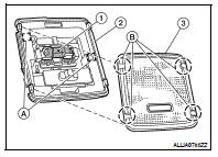
ROOM LAMP (if equipped)
Removal
1. Disconnect the negative battery terminal.
2. Insert a suitable tool between headlining and room lamp (2) to release the clips (A).
3. Disconnect the room lamp connector, then remove the room lamp (2).
Installation
Installation is in the reverse order of removal.
Bulb Replacement
1. Disconnect the negative battery terminal.
2. Using a suitable tool, release the pawls (B) and remove room lamp lens (3) from room lamp (2).
3. Pull bulb (1) straight out to remove.

PERSONAL LAMP REAR (if equipped)
Removal
The personal lamp rear (RH/LH) (1) is replaced as part of the headlining assembly. Refer to INT-42, "Removal and Installation".

Installation
Installation is in the reverse order of removal.
Bulb Replacement
1. Disconnect the negative battery terminal.
2. Using a suitable tool, release the pawls and remove personal lamp rear lens (3) 3. Pull bulb (2) straight out to remove.

 On-vehicle repair
 Illumination