Nissan Altima (L32) 2007-2012 Service Manual: Line pressure test
Inspection and Judgment
INSPECTION
Line Pressure Test Port
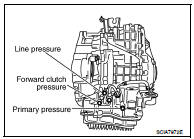
Line Pressure Test Procedure
1. Inspect the amount of engine oil and replenish if necessary.
2. Drive the car for about 10 minutes to warm it up so that the CVT fluid reaches in the range of 50 to 80°C (122 to 176°F), then inspect the amount of CVT fluid and replenish if necessary.
NOTE: The CVT fluid temperature rises in the range of 50 to 80°C (122 to 176°F) during 10 minutes of driving.
3. After warming up CVT, remove the oil pressure detection plug and install the oil pressure gauge [special service tool: — (OTC3492)].
CAUTION: When using the oil pressure gauge, be sure to use the O-ring attached to the oil pressure detection plug. 4. Securely engage the parking brake so that the tires do not turn.

5. Start the engine, and then measure the line pressure at both idle and the stall speed.
CAUTION: • Keep the brake pedal pressed all the way down during measurement.
• When measuring the line pressure at the stall speed. Refer to TM-261, "Stall Speed".

Line pressure: Refer to TM-261, "Line Pressure".
6. After the measurements are complete, install the oil pressure detection plug and tighten to the specified torque below.

CAUTION: • Do not reuse O-ring.
• Apply CVT fluid to O-ring.
Line Pressure
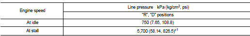
*1: Reference values
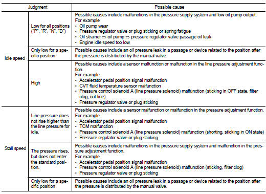
JUDGMENT
 Stall test
 Road test