Nissan Altima (L32) 2007-2012 Service Manual: Lock-up and select control system
System Diagram
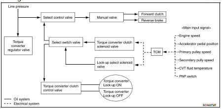
System Description
• The torque converter clutch piston in the torque converter is engaged to eliminate torque converter slip to increase power transmission efficiency.
• The torque converter clutch control valve operation is controlled by the torque converter clutch solenoid valve, which is controlled by a signal from TCM. The torque converter clutch control valve engages or releases the torque converter clutch piston.
• When shifting between “N” (“P”) ⇔ “D” (“R”), torque converter clutch solenoid controls engagement power of forward clutch and reverse brake.
• The lock-up applied gear range was expanded by locking up the torque converter at a lower vehicle speed than conventional CVT models.
TORQUE CONVERTER CLUTCH AND SELECT CONTROL VALVE CONTROL
Lock-up Released
In the lock-up released state, the torque converter clutch control valve is set into the unlocked state by the torque converter clutch solenoid and the lock-up apply pressure is drained.
In this way, the torque converter clutch piston is not coupled.
Lock-up Applied
In the lock-up applied state, the torque converter clutch control valve is set into the locked state by the torque converter clutch solenoid and lock-up apply pressure is generated.
In this way, the torque converter clutch piston is pressed and coupled.
Select Control
When shifting between “N” (“P”) ⇔ “D” (“R”), optimize the operating pressure on the basis of the throttle position, the engine speed, and the secondary pulley (output) revolution speed to lessen the shift shock.
Component Parts Location - Coupe
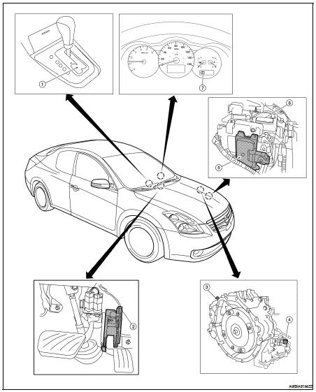
1. Control device assembly (Manual mode select switch and manual mode position select switch)
2. Accelerator pedal position (APP) sensor
3. Secondary speed sensor
4. CVT unit harness connector
5. TCM
6. Battery
7. Shift position indicator Manual mode indicator
Component Parts Location - Sedan
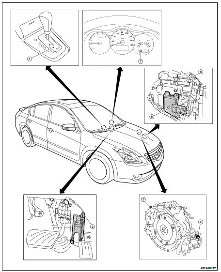
1. Control device assembly (Manual mode select switch and manual mode position select switch)
2. Accelerator pedal position (APP) sensor
3. Secondary speed sensor
4. CVT unit harness connector
5. TCM
6. Battery
7. Shift position indicator Manual mode indicator
Component Description
TRANSAXLE ASSEMBLY
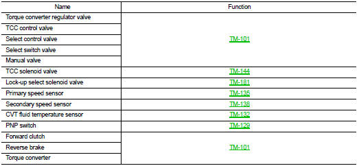
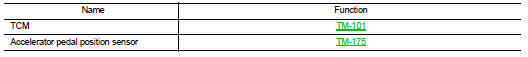
EXCEPT TRANSAXLE ASSEMBLY
 Control system
 Shift mechanism