Nissan Altima (L32) 2007-2012 Service Manual: Mainshaft AND Gear
Exploded View
Refer to TM-28, "Exploded View".
Disassembly
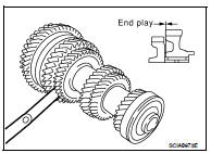
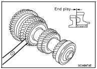
1. Before disassembling, measure the end play of 1st and 2nd main gears.
End play standard value : Refer to TM-83, "End Play".
2. Remove snap ring.
3. Remove C-ring holder and then remove mainshaft C-ring.
4. Press out mainshaft rear bearing, 6th main gear adjusting shim, and 6th main gear using Tool and a puller.
Tool number : ST33052000 ( — )
5. Remove 5th-6th mainshaft spacer.
6. Press out 4th main gear and 5th main gear using Tool and a puller.
Tool number : ST33052000 ( — )
7. Remove 4th main gear adjusting shim.
8. Remove 3rd-4th mainshaft spacer.
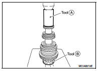
9. Press out 3rd main gear and 2nd main gear using Tool (A) and a puller (B).
Tool number : KV40105020 ( — )
10. Remove 2nd needle bearing.
11. Press out 2nd main gear bushing, 1st-2nd synchronizer hub assembly, 1st main gear, 1st needle bearing, 1st main gear bushing, and reverse main gear using Tool (A).
Tool number : KV40105020 ( — )
Assembly
1. Press in reverse main gear using Tools.
CAUTION: • Be careful with orientation of reverse main gear.
• Do not reuse reverse main gear.
2. Press in 1st main gear bushing using Tools.
3. Install 1st needle bearing and then 1st main gear.
4. Install 1st-2nd spread spring, 1st-2nd shifting insert, and 1st-2nd synchronizer hub onto 1st-2nd coupling sleeve.
CAUTION: • Be careful with orientation of 1st-2nd synchronizer hub.
• Do not reuse 1st-2nd synchronizer hub and 1st-2nd coupling sleeve.
• Replace 1st-2nd synchronizer hub and 1st-2nd coupling sleeve as a set.
• Be careful with orientation of 1st-2nd coupling sleeve.
• Be sure not to hook center projection of 2 spread springs on same 1st-2nd shifting insert.
5. Install 1st inner baulk ring, 1st synchronizer cone, and 1st outer baulk ring onto mainshaft and then press in 1st-2nd synchronizer hub assembly onto mainshaft using Tools.
CAUTION: • Outer baulk ring, synchronizer cone, and inner baulk ring on 2nd gear-side must have been removed.
• Be careful with orientation of coupling sleeve.
• Replace 1st inner baulk ring, 1st synchronizer cone, and 1st outer baulk ring as a set.
6. Press in 2nd main gear bushing using Tools.
7. Install 2nd outer baulk ring, 2nd synchronizer cone, and 2nd inner baulk ring.
CAUTION: Replace 2nd outer baulk ring, 2nd synchronizer cone, and 2nd inner baulk ring as a set. 8. Install 2nd needle bearing and 2nd main gear.
9. Press in 3rd main gear using Tools.
CAUTION: • Be careful with orientation of 3rd main gear.
• Do not reuse 3rd main gear.
10. Install 3rd-4th mainshaft spacer.
11. Select 4th main gear adjusting shim so that dimension “C1” satisfies the standard value below and install 4th main gear adjusting shim onto mainshaft.
Standard value for dimension “C1” : Refer to TM-84, "Dimension".
CAUTION: Only one adjusting shim can be selected.
12. Press in 4th main gear using Tools.
Tool numbers : ST33200000 (J-26082) : ST30901000 (J-26010-01)
CAUTION: • Be careful with orientation of 4th main gear.
• Do not reuse 4th main gear.
13. Press in 5th main gear using Tools.
Tool numbers : ST33200000 (J-26082) : ST30901000 (J-26010-01)
CAUTION: • Be careful with orientation of 5th main gear.
• Do not reuse 5th main gear.
14. Install 5th-6th mainshaft spacer.
15. Press in 6th main gear using Tools (A) and (B).
Tool numbers A: ST33200000 (J-26082) B: ST30901000 (J-26010-01)
CAUTION: Do not reuse 6th main gear.
16. Select 6th main gear adjusting shim and then install it onto mainshaft.
• Calculate thickness “S” of 6th main gear adjusting shim following the procedure below so that end play dimension between 6th main gear and mainshaft rear bearing becomes the dimension shown below.
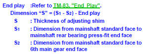
CAUTION: Only one adjusting shim can be selected.
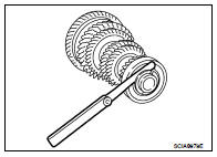
a. Measure dimension “S1” and “S2” using a height gauge (A) and pick tester (B).
b. Install selected 6th main gear adjusting shim to mainshaft.
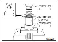
17. Press in mainshaft rear bearing using Tools.
Tool numbers A: ST30720000 (J-25405) B: ST30901000 (J-26010-01)
18. Install mainshaft C-ring onto mainshaft and check that end play of mainshaft rear bearing satisfies the standard value.
End play standard value : Refer to TM-83, "End Play".
• If measurement is outside the standard range, reselect mainshaft C-ring.
19. Install C-ring holder and then install snap ring. CAUTION: Do not reuse snap ring.
20. Check end play of 1st and 2nd main gears.
End play standard value : Refer to TM-83, "End Play".
Inspection
MAINSHAFT AND GEAR
Check items below. If necessary, replace them with new ones.
• Damage, peeling, dent, uneven wear, bending, and other nonstandard conditions of the shaft.
• Excessive wear, damage, peeling, and other non-standard conditions of the gears.
SYNCHRONIZER
Synchronizer Hub and Coupling Sleeve
Check items below. If necessary, replace them with new ones.
• Damage and unusual wear on contact surfaces of coupling sleeve, synchronizer hub and shifting insert.
• Coupling sleeve and synchronizer hub must move smoothly.
Baulk Ring and Spread Spring
Check items below. If necessary, replace them with new ones.
• If any crack, damage, or excessive wear is found on cam face of baulk ring or working face of insert, replace it.
Baulk Ring Clearance for Triple Cone Synchronizer (1st and 2nd)
• Check the clearance between outer baulk ring, synchronizer cone, and inner baulk ring as follows. CAUTION: The clearances “A”, “B”, and “C” are controlled with outer baulk ring, synchronizer cone, and inner baulk ring as a set.
Replace them as a set if the clearances are outside the limit value.
1. Measure the clearance “A” at two points or more diagonally opposite using a feeler gauge (B) when pressing outer baulk ring (1), synchronizer cone (2), and inner baulk ring (3) toward gear taper cone (C). Then calculate mean value.
2. Measure the clearance “B” at two points or more diagonally opposite using a feeler gauge. Then calculate mean value.
3. Measure the clearance “C” at two points or more diagonally opposite using a feeler gauge (A) when pressing outer baulk ring (1), synchronizer cone (2), and inner baulk ring (3) toward gear taper cone (B). Then calculate mean value.
BEARING
Check bearing for damage and rough rotation. If necessary, replace with new one.
 Input shaft and gear
 Reverse idler shaft and gear