Nissan Altima (L32) 2007-2012 Service Manual: Reverse idler shaft and gear
Exploded View
Refer to TM-28, "Exploded View".
Disassembly
1. Remove reverse idler gear (Rear), reverse coupling sleeve, and reverse insert spring simultaneously.
2. Remove reverse idler gear needle bearing.
3. Remove thrust needle bearing.
4. Remove reverse baulk ring.
5. Remove reverse idler gear (Front).
6. Remove reverse idler gear needle bearing.
7. Remove thrust needle bearing.
8. Remove retaining pin from reverse idler shaft.
Assembly
Assembly is in the reverse order of disassembly.

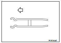
CAUTION: • Be careful with orientation of reverse insert spring.
• Do not reuse retaining pin.
Inspection
REVERSE IDLER SHAFT AND GEAR
Check items below. If necessary, replace them with new ones.
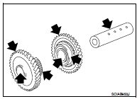
• Damage, peeling, dent, uneven wear, bending, and other nonstandard conditions of the shaft.
• Excessive wear, damage, peeling, and other non-standard conditions of the gears.
SYNCHRONIZER
Synchronizer Hub and Coupling Sleeve
Check items below. If necessary, replace them with new ones.
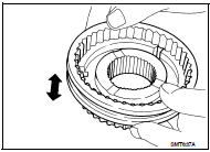
• Damage and unusual wear on contact surfaces of coupling sleeve, synchronizer hub of reverse idler gear (Rear), and insert spring.
• Coupling sleeve and synchronizer hub of reverse idler gear (Rear) must move smoothly.
Baulk Ring
Check items below. If necessary, replace them with new ones.
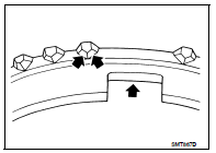
• If any crack, damage, or excessive wear is found on cam face of baulk ring or working face of insert, replace it.
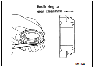
Baulk Ring Clearance for Single Cone Synchronizer (Reverse)
• Push baulk ring on the cone and measure the clearance between baulk ring and cone. If the measurement is below limit, replace it with a new one.

BEARING
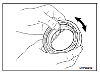
Check bearing for damage and rough rotation. If necessary, replace with new one.

 Mainshaft AND Gear
 Final drive