Nissan Altima (L32) 2007-2012 Service Manual: Malfunction indicator lamp
Description
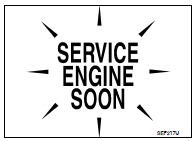
The Malfunction Indicator Lamp (MIL) is located on the combination
meter.
The MIL will light up when the ignition switch is turned ON without
the engine running. This is a bulb check.
When the engine is started, the MIL should go off. If the MIL remains
on, the on board diagnostic system has detected an engine system
malfunction.
For details, refer to EC-968, "Diagnosis Procedure".
Component Function Check
1.CHECK MIL FUNCTION
1. Turn ignition switch ON.
2. Make sure that MIL lights up.
Is the inspection result normal?
YES >> INSPECTION END
NO >> Go to EC-968, "Diagnosis Procedure".
Diagnosis Procedure
1.CHECK DTC
Check that DTC UXXXX is not displayed.
Is the inspection result normal?
YES >> GO TO 2.
NO >> Perform trouble diagnosis for DTC UXXXX.
2.CHECK DTC WITH METER
Refer to MWI-38, "CONSULT-III Function (METER/M&A)".
Is the inspection result normal?
YES >> GO TO 3.
NO >> Repair or replace.
3.CHECK INTERMITTENT INCIDENT
Refer to GI-42, "Intermittent Incident".
Is the inspection result normal?
YES >> Replace combination meter.
NO >> Repair or replace.
Description
The ignition signal from the ECM is sent to and amplified by the power
transistor. The power transistor turns
ON and OFF the ignition coil primary circuit. This ON/OFF operation induce ...
Description
From the beginning of refueling, the air and vapor inside the fuel tank go
through refueling EVAP vapor cut
valve and EVAP/ORVR line to the EVAP canister. The vapor is absorbed by t ...
Other materials: Jacking up vehicle and removing
the damaged tire (2WD models)
WARNING
Never get under the vehicle while it is
supported only by the jack. If it is necessary
to work under the vehicle,
support it with safety stands.
Use only the jack provided with your
vehicle to lift the vehicle. Do not use
the jack provided with your vehicle
on other vehicles. The ja ...
Intelligent Around View Monitor
system operation
With the ignition switch in the ON position,
move the shift lever to the R (Reverse) position
or press the CAMERA button to operate
the Intelligent Around View Monitor.
The screen displayed on the Intelligent
Around View Monitor will automatically return
to the previous screen 3 minutes after
the C ...
How to switch the display
With the ignition switch in the ON position,
press the CAMERA button or move the shift
lever to the R (Reverse) position to operate
the Intelligent Around View Monitor.
The Intelligent Around View Monitor displays
different split screen views depending
on the position of the shift lever. Press
the ...


 Ignition signal
 On board refueling vapor recovery
(ORVR)