Nissan Altima (L32) 2007-2012 Service Manual: Mechanical system
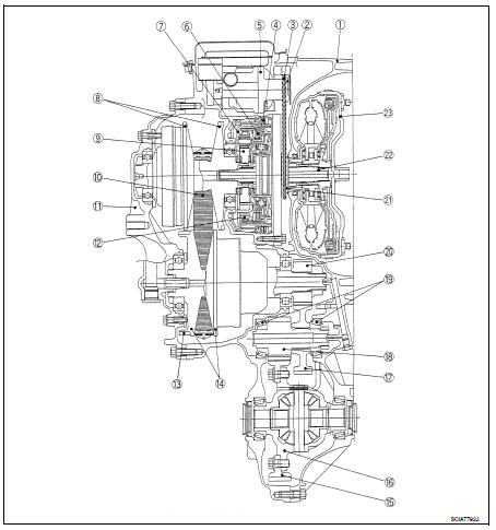
Cross-Sectional View
1. Converter housing
2. Driven sprocket
3. Chain
4. Reverse brake
5. Oil pump
6. Forward clutch
7. Planetary carrier
8. Primary pulley
9. Sun gear
10. Steel belt
11. Side cover
12. Internal gear
13. Parking gear
14. Secondary pulley
15. Final gear
16. Differential case
17. Idler gear
18. Reduction gear
19. Taper roller bearing
20. Output gear
21. Drive sprocket
22. Input shaft
23. Torque converter
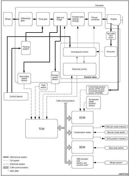
System Diagram
System Description
Transmits the power from the engine to the drive wheel.
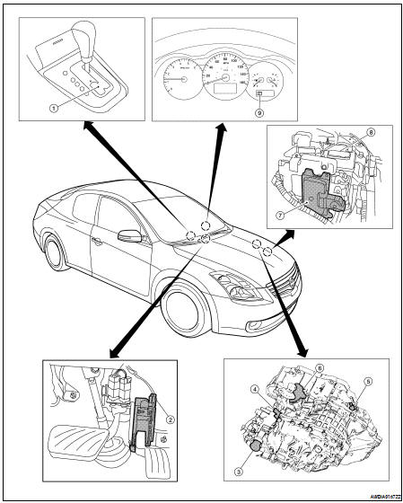
Component Parts Location - Coupe
1. Control device assembly
2. Accelerator pedal position sensor
3. CVT unit harness connector
4. Primary speed sensor
5. Secondary speed sensor
6. PNP switch
7. TCM
8. Battery
9. Shift position indicator
Manual mode indicator
Component Parts Location - Sedan
1. Control device assembly
2. Accelerator pedal position sensor
3. CVT unit harness connector
4. Primary speed sensor
5. Secondary speed sensor
6. PNP switch
7. TCM
8. Battery
9. Shift position indicator
Manual mode indicator
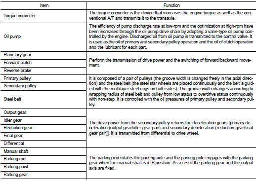
Component Description
System Diagram
Component Parts Location - Coupe
1. Control device assembly
2. Accelerator pedal position sensor
3. CVT unit harness connector
4. Primary speed sensor
5. Secondary speed senso ...
System Diagram
System Description
The hydraulic control mechanism consists of the oil pump directly driven by
the engine, the hydraulic control
valve that controls line pressure and transmiss ...
Other materials: NISSAN Vehicle Immobilizer System
The NISSAN Vehicle Immobilizer System
will not allow the engine to start without
the use of a registered key.
If the engine fails to start using a registered
key (for example, when interference is
caused by another registered key, an automated
toll road device or automatic payment
device on the key ...
Fuel gauge
The gauge indicates the approximate fuel
level in the tank.
The gauge may move slightly during braking,
turning, acceleration, or going up or
down hills.
The gauge needle returns to 0 (Empty) after
the ignition switch is placed in the OFF
position.
The low fuel warning message shows in
the vehic ...
Headlight control switch
Type A (if so equipped)
Lighting
Rotate the switch to the
position,
and the front parking, tail, license plate,
and instrument panel lights will come
on. The will illuminate in the
meter.
Rotate the switch to the
position,
and the headlights will come on and all
the other lights re ...

 CVT system
 Hydraulic control system