Nissan Altima (L32) 2007-2012 Service Manual: Oil cooler
Removal and Installation
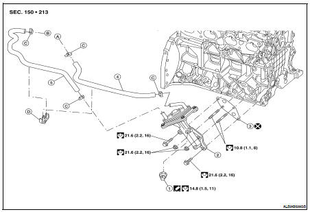
1. Oil pressure switch
2. Oil cooler
3. Gasket
4. Water hose (outlet)
5. Water hose (inlet)
A. To water control valve housing
B. To heater pipe assembly
C. Hose clamp
D. Clip
WARNING: Be careful not to get burned, engine coolant and engine oil may be hot.
CAUTION: • When removing oil cooler, prepare a shop cloth to absorb any engine oil leakage or spillage.
• Completely wipe off any engine oil that adheres to the engine and the vehicle.
REMOVAL
1. Drain engine oil. Refer to LU-10, "Changing Engine Oil".
2. Drain engine coolant. Refer to CO-12, "Changing Engine Coolant".
CAUTION: Do not spill coolant on the drive belt.
3. Disconnect water hoses from oil cooler.
NOTE: For reference during installation, put matching marks on oil cooler hoses.
4. Remove oil cooler.
INSPECTION AFTER REMOVAL
1. Check oil cooler for cracks.
2. Check oil cooler for clogging by blowing through coolant inlet. If necessary, replace oil cooler assembly.
INSTALLATION
Installation is in the reverse order of removal.
• Remove any old liquid gasket adhering to the oil pressure switch and oil cooler before installing the oil pressure switch.
INSPECTION AFTER INSTALLATION
Start engine and check for leaks of engine oil or coolant.
 Oil pump
 Service data and specifications
(SDS)
Service data and specifications
(SDS)