Nissan Altima (L32) 2007-2012 Service Manual: Oil pump
Removal and Installation
• The oil pump is part of the front cover. For removal and installation of the oil pump, it is necessary to remove and install the front cover. Refer to EM-52, "Removal and Installation".
Disassembly and Assembly
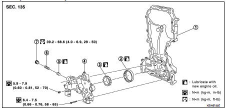
1. Front cover
2. Outer rotor
3. Inner rotor
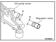
4. Oil pump cover
5. Regulator valve
6. Spring
7. Regulator plug
CAUTION: Before assembly, apply new engine oil to the parts as shown above.
DISASSEMBLY
1. Remove the oil pump cover.
2. Remove inner rotor and outer rotor from front cover.
3. After removing regulator plug, remove regulator spring and regulator valve.
INSPECTION AFTER DISASSEMBLY
Measure the clearance of the oil pump parts to check they are within specification.
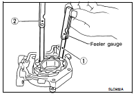
1. Measure clearance with feeler gauge as follows: • Clearance between outer rotor and oil pump body (position 1).
Standard : 0.114 - 0.179 mm (0.0045 - 0.0070 in)
• Tip clearance between inner rotor and outer rotor (position 2).
Standard : 0.170 - 0.220 mm (0.0067 - 0.0087 in)
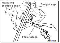
2. Measure clearance with feeler gauge and straightedge as follows: • Side clearance between inner rotor and oil pump body (position 3).
Standard : 0.030 - 0.070 mm (0.0012 - 0.0028 in)
• Side clearance between outer rotor and oil pump body (position 4).
Standard : 0.060 - 0.110 mm (0.0024 - 0.0043 in)
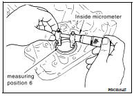
3. Calculate the clearance between inner rotor and oil pump body as follows: • Measure the outer diameter of protruded portion of inner rotor (Position 5).
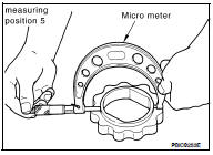
• Measure the inner diameter of oil pump body with inside micrometer (Position 6).
• (Clearance) = (Inner diameter of oil pump body) – (Outer diameter of inner rotor).
Standard : 0.035 - 0.070 mm (0.0014 - 0.0028 in)
4. Calculate regulator valve clearance as follows: • (Clearance) = D1(Valve hole diameter) – D2 (Outer diameter of valve)
Standard : 0.040 - 0.097 mm (0.0016 - 0.0038 in)
CAUTION: Coat regulator valve with engine oil.
Check that it falls smoothly into the valve hole by its own weight.
ASSEMBLY
Assembly is in the reverse order of disassembly.
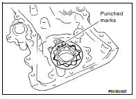
• Install the inner rotor and outer rotor with the punched marks on the oil pump cover side.
CAUTION: Before assembly apply new engine oil to the parts as specified.
 On-vehicle repair
 Oil cooler