Nissan Altima (L32) 2007-2012 Service Manual: Oil pan and oil strainer
Removal and Installation
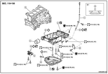
1. Oil level gauge guide
2. Oil pan, upper
3. Cylinder block
4. Oil filter
5. Oil strainer
6. Drain plug
7. Oil pan, lower
8. Rear plate cover
9. O-ring
A. To oil pan, lower
REMOVAL
WARNING: To avoid the danger of being scalded, never drain the engine oil when the engine is hot.
1. Drain engine oil. Refer to LU-10, "Changing Engine Oil".
2. Remove the front exhaust tube. Refer to EX-5, "Exploded View".
3. Remove power steering cooler hose bracket from suspension member.
4. Remove the front suspension member for clearance to remove the oil pan. Refer to FSU-13, "Removal and Installation".
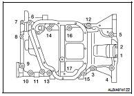
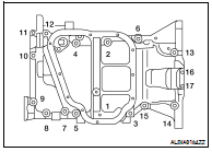
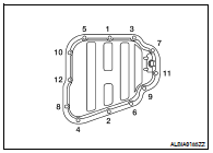
5. Remove the lower oil pan bolts in the order as shown, using power tool.
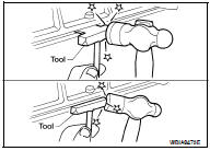
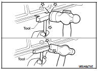
6. Remove the lower oil pan using Tool.
NOTE: Tap gently to cut sealant around the pan; do not damage the mating surface using Tool.
Tool number : KV10111100 (J-37228)
7. Remove the oil strainer.
8. Remove rear plate cover, and four engine-to transaxle bolts, using power tool.
9. Loosen the upper oil pan bolts in the order shown to remove upper oil pan, using power tool.
10. Remove upper oil pan using Tool.
NOTE: Tap gently to cut sealant around the pan; do not damage the mating surface using Tool.
Tool number : KV10111100 (J-37228)
INSPECTION AFTER REMOVAL
• Clean the oil strainer screen to remove any foreign material.
INSTALLATION
Installation is in the reverse order of removal.
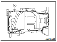
• Apply Genuine Silicone RTV Sealant or equivalent to the upper oil pan at the specified sealant bead diameter (A) as shown. Refer to GI-15, "Recommended Chemical Products and Sealants".
Sealant bead diameter (A) : 4.0 - 5.0 mm (0.157 - 0.197 in)
CAUTION: Install two new O-rings in the upper oil pan.
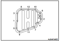
• Tighten the upper oil pan bolts in the order as shown.
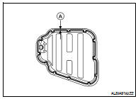
• Apply Genuine Silicone RTV Sealant or equivalent to the lower oil pan at the specified sealant bead diameter (A) as shown. Refer to GI-15, "Recommended Chemical Products and Sealants".
Sealant bead diameter (A) : 4.0 - 5.0 mm (0.157 - 0.197 in)
Tighten the lower oil pan bolts in the numerical order shown.
CAUTION: Wait at least 30 minutes after the oil pans are installed before filling the engine with oil.
INSPECTION AFTER INSTALLATION
• Check for any engine oil leaks with the engine at operating temperature and running at idle.
 Exhaust manifold and three way
catalyst
Exhaust manifold and three way
catalyst Ignition coil