Nissan Altima (L32) 2007-2012 Service Manual: Exhaust manifold and three way catalyst
Removal and Installation
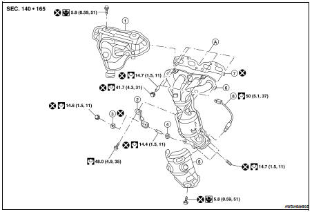
1. Exhaust manifold cover (upper)
2. Exhaust manifold stay
3. Manifold yoke (type B)
4. Manifold yoke (type A)
5. Exhaust manifold cover (lower)
6.. Exhaust manifold and three way catalyst assembly
7. Exhaust manifold gasket
8. Air fuel ratio (A/F) sensor 1
A. To cylinder head
REMOVAL
1. Remove the engine undercover using power tools.
2. Disconnect the electrical connector of air fuel ratio (A/F) sensor 1, and unhook the harness from the bracket and middle clamp on the cover.
3. Remove the air fuel ratio (A/F) sensor 1 using Tools.
Tool numbers : — (J-44626) : KV10117100 (J-36471-A)
CAUTION: • Be careful not to damage air fuel ratio (A/F) sensor.
• Discard any air fuel ratio (A/F) sensor which has been dropped from a height of more than 0.5 m (19.7 in) onto a hard surface such as a concrete floor; replace with a new one.
4. Remove the exhaust manifold cover (lower).
5. Remove the exhaust front tube. Refer to EX-6, "Removal and Installation".
6. Remove the exhaust manifold cover (upper).
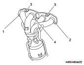
7. Loosen the nuts in the reverse order as shown, on the exhaust manifold and three way catalyst assembly.
8. Remove the exhaust manifold and three way catalyst assembly and gasket. Discard the gasket.
INSPECTION AFTER REMOVAL
Surface Distortion
• Use a reliable straightedge and feeler gauge to check the flatness of exhaust manifold fitting surface.
Limit : 0.3 mm (0.012 in)
INSTALLATION
Installation is in the reverse order of removal.
Tightening Exhaust Manifold Nuts
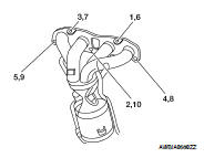
• Tighten the nuts to specification in the numerical order shown, on the exhaust manifold and three way catalyst assembly.
Installation of Air Fuel Ratio (A/F) Sensor 1
Clean the air fuel ratio (A/F) sensor 1 threads with the Tool, then apply the anti-seize lubricant to the threads before installing the air fuel ratio (A/F) sensor 1.
Tool number : J-43897 - 18
: J-43897 - 12
CAUTION: Do not over-tighten the air fuel ratio (A/F) sensor 1. Doing so may cause damage to the air fuel ratio (A/ F) sensor 1, resulting in a malfunction and the MIL coming on.
 Intake manifold
 Oil pan and oil strainer