Nissan Altima (L32) 2007-2012 Service Manual: Diagnosis system (TCM)
CONSULT-III Function (TRANSMISSION)
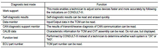
CONSULT-III can display each diagnostic item using the diagnostic test
modes shown below
FUNCTION
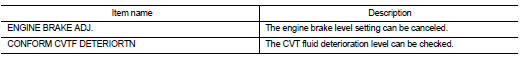
WORK SUPPORT MODE
Display Item List
Engine Brake Adjustment
CAUTION:
Mode of “+1”“0”“−1”“−2”“OFF” can be selected by pressing the “UP”“DOWN” on
CONSULT-III screen.
However, do not select mode other than “0” and “OFF”. If the “+1” or “−1” or
“–2” is selected, that
might cause the irregular driveability.
Check CVT Fluid Deterioration Date
CAUTION:
Touch “CLEAR” after changing CVT fluid, and then erase “CVTF DETERIORATION
DATE”.
SELF-DIAGNOSTIC RESULT MODE
After performing self-diagnosis, place check marks for results on the TM-264,
"Diagnostic Work Sheet". Reference
pages are provided following the items.
Display Items List
Refer to TM-399, "DTC Index".
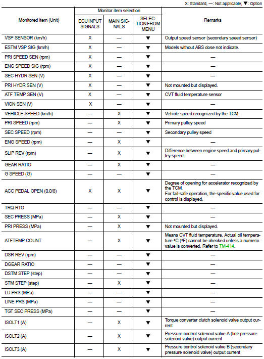
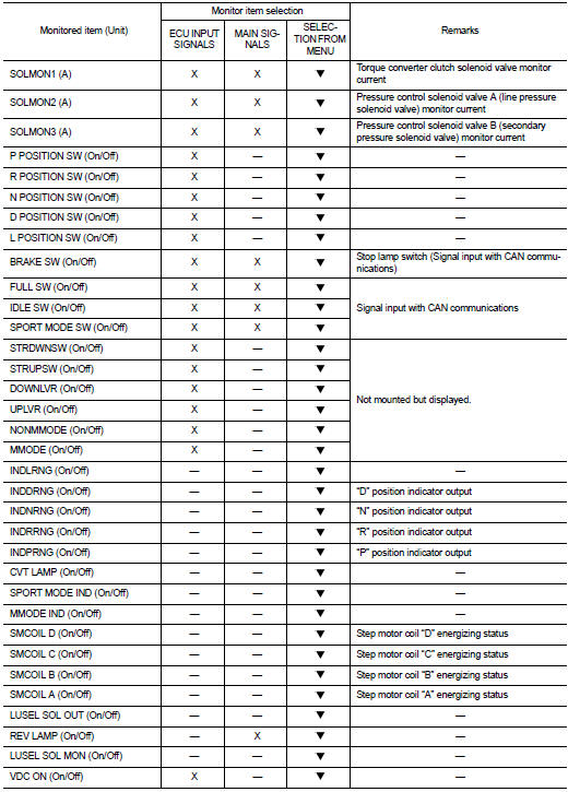
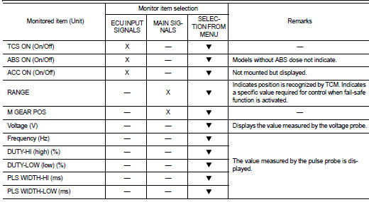
DATA MONITOR MODE
Display Items List
Diagnostic Tool Function
OBD-II SELF-DIAGNOSTIC
PROCEDURE (WITH GST)
Refer to EC-134, "Diagnosis Tool Function" (for California), EC-663,
"Diagnosis Tool Function" (except for
California)
Diagnosis Description
DESCRIPTION
The CVT system has two self-diagnostic systems.
The first is the emission-related on board diagnostic system (OBD-II) performed
by the TCM in combination
wit ...
 OBD-II SELF-DIAGNOSTIC
PROCEDURE (WITH GST)
OBD-II SELF-DIAGNOSTIC
PROCEDURE (WITH GST) On board diagnostic (OBD) System
 Component diagnosis