Nissan Altima (L32) 2007-2012 Service Manual: P0101 maf sensor
Description
The mass air flow sensor (1) is placed in the stream of intake air. It measures the intake flow rate by measuring a part of the entire intake flow. The mass air flow sensor controls the temperature of the hot wire to a certain amount. The heat generated by the hot wire is reduced as the intake air flows around it. The more air, the greater the heat loss.
Therefore, the electric current supplied to hot wire is changed to maintain the temperature of the hot wire as air flow increases. The ECM detects the air flow by means of this current change.
DTC Logic
DTC DETECTION LOGIC
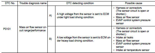
DTC CONFIRMATION PROCEDURE
1.PRECONDITIONING
If DTC Confirmation Procedure has been previously conducted, always turn ignition switch OFF and wait at least 10 seconds before conducting the next test.
If engine will not start or stops soon, wait at least 10 seconds with engine stopped (Ignition switch ON) instead of running engine at idle speed.
>> GO TO 2.
2.PERFORM DTC CONFIRMATION PROCEDURE FOR MALFUNCTION A
1. Start engine and warm it up to normal operating temperature.
2. Run engine for at least 10 seconds at idle speed.
3. Check 1st trip DTC.
Is 1st trip DTC detected? YES >> Go to EC-695, "Diagnosis Procedure".
NO-1 >> With CONSULT-III: GO TO 3.
NO-2 >> Without CONSULT-III: GO TO 5.
3.CHECK MASS AIR FLOW SENSOR FUNCTION
1. Turn ignition switch ON.
2. Start engine and warm it up to normal operating temperature.
If engine cannot be started, go to EC-695, "Diagnosis Procedure".
3. Select “DATA MONITOR” mode with CONSULT-III.
4. Check the voltage of “MAS A/F SE-B1” with “DATA MONITOR”.
5. Increases engine speed to about 4,000 rpm.
6. Monitor the linear voltage rise in response to engine speed increases.
Is the inspection result normal? YES >> GO TO 4.
NO >> Go to EC-695, "Diagnosis Procedure".
4.PERFORM DTC CONFIRMATION PROCEDURE FOR MALFUNCTION B
1. Maintain the following conditions for at least 10 consecutive seconds.
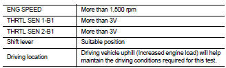
CAUTION: Always drive vehicle at a safe speed.
2. Check 1st trip DTC.
Is 1st trip DTC detected? YES >> Go to EC-695, "Diagnosis Procedure".
NO >> INSPECTION END
5.PERFORM COMPONENT FUNCTION CHECK FOR MALFUNCTION B
Perform component function check. Refer to EC-694, "Component Function Check".
NOTE: Use component function check to check the overall function of the mass air flow sensor circuit. During this check, a DTC might not be confirmed.
Is the inspection result normal? YES >> INSPECTION END NO >> Go to EC-695, "Diagnosis Procedure".
Component Function Check
1.PERFORM COMPONENT FUNCTION CHECK FOR MALFUNCTION B

1. Start engine and warm it up to normal operating temperature.
2. Select Service $01 with GST.
3. Check the mass air flow sensor signal with Service $01.
4. Check for linear mass air flow sensor signal value rise in response to increases to about 4,000 rpm in engine speed.
Is the inspection result normal? YES >> INSPECTION END
NO >> Go to EC-695, "Diagnosis Procedure".
Diagnosis Procedure
1.INSPECTION START
Confirm the detected malfunction (A or B). Refer to EC-693, "DTC Logic".
Which malfunction is detected? A >> GO TO 3.
B >> GO TO 2.
2.CHECK INTAKE SYSTEM
Check the following for connection.
• Air duct
• Vacuum hoses
• Intake air passage between air duct and intake manifold
Is the inspection result normal? YES >> GO TO 3.
NO >> Reconnect the parts.
3.CHECK GROUND CONNECTION
1. Turn ignition switch OFF.
2. Check ground connection E9. Refer to Ground Inspection in GI-45, "Circuit Inspection".
Is the inspection result normal? YES >> GO TO 4.
NO >> Repair or replace ground connection.
4.CHECK MAF SENSOR POWER SUPPLY CIRCUIT
1. Disconnect mass air flow (MAF) sensor harness connector.
2. Turn ignition switch ON.
3. Check the voltage between MAF sensor harness connector and ground.
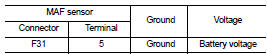
Is the inspection result normal? YES >> GO TO 6.
NO >> GO TO 5.
5.DETECT MALFUNCTIONING PART
Check the following.
• Junction block connector E44
• Harness connector E11,F2
• 15A fuse (No.42)
• Harness for open or short between mass air flow sensor and ECM
• Harness for open or short between mass air flow sensor and IPDM E/R
>> Repair open circuit or short to ground or short to power in harness or connectors.
6.CHECK MAF SENSOR GROUND CIRCUIT FOR OPEN AND SHORT
1. Turn ignition switch OFF.
2. Disconnect ECM harness connector.
3. Check the continuity between MAF sensor harness connector and ECM harness connector.
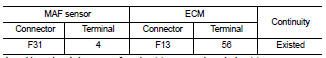
4. Also check harness for short to ground and short to power.
Is the inspection result normal? YES >> GO TO 7.
NO >> Repair open circuit or short to ground or short to power in harness or connectors.
7.CHECK MAF SENSOR INPUT SIGNAL CIRCUIT FOR OPEN AND SHORT
1. Check the continuity between MAF sensor harness connector and ECM harness connector.
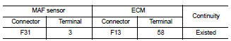
2. Also check harness for short to ground and short to power.
Is the inspection result normal? YES >> GO TO 8.
NO >> Repair open circuit or short to ground or short to power in harness or connectors.
8.CHECK INTAKE AIR TEMPERATURE SENSOR
Check intake air temperature sensor.
Refer to EC-707, "Component Inspection".
Is the inspection result normal? YES >> GO TO 9.
NO >> Replace mass air flow sensor (with intake air temperature sensor).
9.CHECK EVAP CONTROL SYSTEM PRESSURE SENSOR
Refer to EC-824, "Component Inspection".
Is the inspection result normal? YES >> GO TO 10.
NO >> Replace EVAP control system pressure sensor.
10.CHECK MASS AIR FLOW SENSOR
Refer to EC-696, "Component Inspection".
Is the inspection result normal? YES >> GO TO 11.
NO >> Replace mass air flow sensor.
11.CHECK INTERMITTENT INCIDENT
Refer to GI-42, "Intermittent Incident".
>> INSPECTION END
Component Inspection
1.CHECK MASS AIR FLOW SENSOR-I

1. Turn ignition switch OFF.
2. Reconnect all harness connectors disconnected.
3. Start engine and warm it up to normal operating temperature.
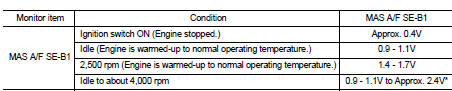
4. Connect CONSULT-III and select “DATA MONITOR” mode.
5. Select “MAS A/F SE-B1” and check indication.
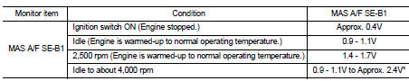
*: Check for linear voltage rise in response to engine being increased to about 4,000 rpm.

1. Turn ignition switch OFF.
2. Reconnect all harness connectors disconnected.
3. Start engine and warm it up to normal operating temperature.
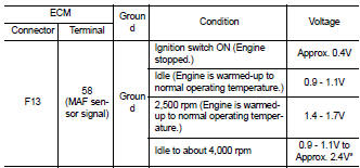
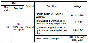
4. Check the voltage between ECM harness connector and ground.
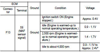
*: Check for linear voltage rise in response to engine being increased to about 4,000 rpm.
Is the inspection result normal? YES >> GO TO 4.
NO >> GO TO 2.
2.CHECK FOR THE CAUSE OF UNEVEN AIR FLOW THROUGH MASS AIR FLOW SENSOR
1. Turn ignition switch OFF.
2. Check for the cause of uneven air flow through mass air flow sensor. Refer to following.
- Crushed air ducts
- Malfunctioning seal of air cleaner element
- Uneven dirt of air cleaner element
- Improper specification of intake air system parts
Is the inspection result normal? YES >> GO TO 4.
NO >> GO TO 3.
3.CHECK MASS AIR FLOW SENSOR-II

1. Repair or replace malfunctioning part.
2. Start engine and warm it up to normal operating temperature.
3. Connect CONSULT-III and select “DATA MONITOR” mode.
4. Select “MAS A/F SE-B1” and check indication.
*: Check for linear voltage rise in response to engine being increased to about 4,000 rpm.

1. Repair or replace malfunctioning part.
2. Start engine and warm it up to normal operating temperature.
3. Check the voltage between ECM harness connector and ground.
*: Check for linear voltage rise in response to engine being increased to about 4,000 rpm.
Is the inspection result normal? YES >> INSPECTION END NO >> GO TO 4.
4.CHECK MASS AIR FLOW SENSOR-III

1. Turn ignition switch OFF.
2. Disconnect mass air flow sensor harness connector and reconnect it again.
3. Start engine and warm it up to normal operating temperature.
4. Connect CONSULT-III and select “DATA MONITOR” mode.
5. Select “MAS A/F SE-B1” and check indication.
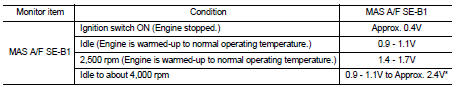
*: Check for linear voltage rise in response to engine being increased to about 4,000 rpm.

1. Turn ignition switch OFF.
2. Disconnect mass air flow sensor harness connector and reconnect it again.
3. Start engine and warm it up to normal operating temperature.
4. Check the voltage between ECM harness connector and ground.
*: Check for linear voltage rise in response to engine being increased to about 4,000 rpm.
Is the inspection result normal? YES >> INSPECTION END
NO >> Clean or replace mass air flow sensor.
 P0075 ivt control solenoid valve
 P0102, p0103 maf sensor