Nissan Altima (L32) 2007-2012 Service Manual: P0075 ivt control solenoid valve
Description
Intake valve timing control solenoid valve is activated by ON/OFF pulse duty (ratio) signals from the ECM.
The intake valve timing control solenoid valve changes the oil amount and direction of flow through intake valve timing control unit or stops oil flow.
The longer pulse width advances valve angle.
The shorter pulse width retards valve angle.
When ON and OFF pulse widths become equal, the solenoid valve stops oil pressure flow to fix the intake valve angle at the control position.
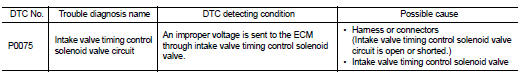
DTC Logic
DTC DETECTION LOGIC
DTC CONFIRMATION PROCEDURE
1.PRECONDITIONING
If DTC Confirmation Procedure has been previously conducted, always turn ignition switch OFF and wait at least 10 seconds before conducting the next test.
>> GO TO2.
2.PERFORM DTC CONFIRMATION PROCEDURE
1. Start engine and let it idle for 5 seconds.
2. Check 1st trip DTC.
Is 1st trip DTC detected? YES >> Go to EC-690, "Diagnosis Procedure".
NO >> INSPECTION END
Diagnosis Procedure
1.CHECK INTAKE VALVE TIMING CONTROL SOLENOID VALVE POWER SUPPLY CIRCUIT
1. Turn ignition switch OFF.
2. Disconnect intake valve timing control solenoid valve harness connector.
3. Turn ignition switch ON.
4. Check the voltage between intake valve timing control solenoid valve harness connector and ground.
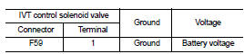
Is the inspection result normal? YES >> GO TO 2.
NO >> Repair open circuit or short to ground or short to power in harness or connectors.
2.CHECK INTAKE VALVE TIMING CONTROL SOLENOID VALVE OUTPUT SIGNAL CIRCUIT FOR OPEN AND SHORT
1. Turn ignition switch OFF.
2. Disconnect ECM harness connector.
3. Check the continuity between intake valve timing control solenoid valve harness connector and ECM harness connector.
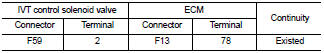
4. Also check harness for short to ground and short to power.
Is the inspection result normal? YES >> GO TO 3.
NO >> Repair open circuit or short to ground or short to power in harness or connectors.
3.CHECK INTAKE VALVE TIMING CONTROL SOLENOID VALVE
Refer to EC-691, "Component Inspection".
Is the inspection result normal? YES >> GO TO 4.
NO >> Replace intake valve timing control solenoid valve.
4.CHECK INTERMITTENT INCIDENT
Refer to GI-42, "Intermittent Incident".
>> INSPECTION END
Component Inspection
1.CHECK INTAKE VALVE TIMING CONTROL SOLENOID VALVE-I
1. Turn ignition switch OFF.
2. Disconnect intake valve timing control solenoid valve harness connector.
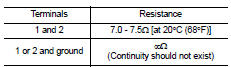
3. Check resistance between intake valve timing control solenoid valve terminals as follows.
Is the inspection result normal? YES >> GO TO 2.
NO >> Replace intake valve timing control solenoid valve.
2.CHECK INTAKE VALVE TIMING CONTROL SOLENOID VALVE-II
1. Remove intake valve timing control solenoid valve.
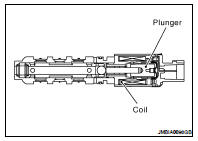
2. Provide 12V DC between intake valve timing control solenoid valve terminals 1 and 2, and then interrupt it. Make sure that the plunger moves as shown in the figure.
CAUTION: Do not apply 12V DC continuously for 5 seconds or more.
Doing so may result in damage to the coil in intake valve timing control solenoid valve.
NOTE: Always replace O-ring when intake valve timing control solenoid valve is removed.
Is the inspection result normal? YES >> INSPECTION END
NO >> Replace intake valve timing control solenoid valve.
 P0037, P0038 HO2S2 Heater
 P0101 maf sensor