Nissan Altima (L32) 2007-2012 Service Manual: P0715 input speed sensor (pri speed sensor)
Description
The input speed sensor (primary speed sensor) detects the primary pulley revolution speed and sends a signal to the TCM.
DTC Logic
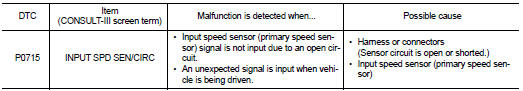
DTC DETECTION LOGIC
DTC CONFIRMATION PROCEDURE
CAUTION: Always drive vehicle at a safe speed.
NOTE: If “DTC CONFIRMATION PROCEDURE” has been previously performed, always turn ignition switch OFF.
Then wait at least 10 seconds before performing the next test.
1.CHECK DTC DETECTION

1. Turn ignition switch ON.
2. Select “DATA MONITOR”.
3. Start engine and maintain the following conditions for at least 5 consecutive seconds.
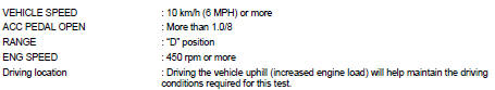

Follow the procedure “With CONSULT-III”.
Is “P0715 INPUT SPD SEN/CIRC” detected? YES >> Go to TM-313, "Diagnosis Procedure".
NO >> Check intermittent incident. Refer to GI-42, "Intermittent Incident".
Diagnosis Procedure
1.CHECK INPUT SPEED SENSOR (PRIMARY SPEED SENSOR)

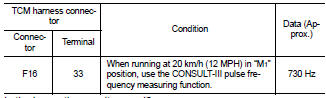
1. Start engine.
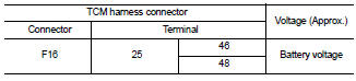
2. Check voltage between TCM harness connector F16 terminal 25, 46 and 25, 48.
3. If OK, check pulse when vehicle cruises.
Is the inspection result normal? YES >> GO TO 12.
NO >> GO TO 2.
2.CHECK POWER AND SENSOR GROUND
1. Turn ignition switch OFF.
2. Disconnect input speed sensor (primary speed sensor) harness connector.
3. Turn ignition switch ON.
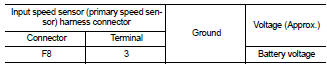
4. Check voltage between input speed sensor (primary speed sensor) harness connector F8 terminal 1 and 3.
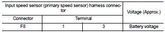
5. Check voltage between input speed sensor (primary speed sensor) harness connector F8 terminal 3 and ground.
Is the inspection result normal? YES >> GO TO 3.
NO-1 >> Battery voltage is not supplied between terminals 1 and 3, terminal 3 and ground: GO TO 6.
NO-2 >> Battery voltage is not supplied between terminals 1 and 3 only: GO TO 8.
3.CHECK HARNESS BETWEEN TCM AND INPUT SPEED SENSOR (PRIMARY SPEED SENSOR) (SENSOR GROUND)
1. Turn ignition switch OFF.
2. Disconnect TCM harness connector and CVT unit harness connector.
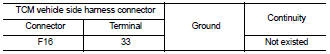
3. Check continuity between TCM harness connector F16 terminal 33 and ground.
Is the inspection result normal? YES >> GO TO 4.
NO >> Repair or replace damaged parts.
4.CHECK HARNESS BETWEEN TCM AND INPUT SPEED SENSOR (PRIMARY SPEED SENSOR) (PART 1)
Check continuity between TCM harness connector F16 (A) terminal 33 and input speed sensor (primary speed sensor) harness connector F8 (B) terminal 2.
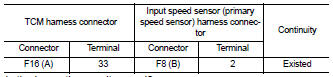
Is the inspection result normal? YES >> GO TO 5.
NO >> Repair or replace damaged parts.
5.CHECK HARNESS BETWEEN TCM AND INPUT SPEED SENSOR (PRIMARY SPEED SENSOR) (PART 2)
Check continuity between TCM harness connector F16 terminal 33 and ground.
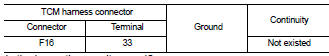
Is the inspection result normal? YES >> GO TO 10.
NO >> Repair or replace damaged parts.
6.CHECK HARNESS BETWEEN IPDM E/R AND INPUT SPEED SENSOR (PRIMARY SPEED SENSOR) (POWER) (PART 1)
1. Turn ignition switch OFF.
2. Disconnect IPDM E/R connector F10.
3. Check continuity between IPDM E/R harness connector F10 terminal 58 and input speed sensor (primary speed sensor) harness connector F8 terminal 3.
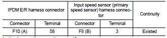
Is the inspection result normal?
YES >> GO TO 7.
NO >> Repair or replace damaged parts.
7.CHECK HARNESS BETWEEN IPDM E/R AND INPUT SPEED SENSOR (PRIMARY SPEED SENSOR) (POWER) (PART 2)
Check continuity between IPDM E/R harness connector F10 terminal 58 and ground.

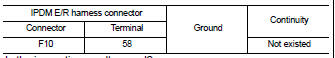
Is the inspection result normal? YES >> Check the following.
• Harness for short or open between ignition switch and IPDM E/R
• 10A fuse (No. 34, located in IPDM E/R) • Ignition switch
NO >> Repair or replace damaged parts.
8.CHECK HARNESS BETWEEN TCM AND INPUT SPEED SENSOR (PRIMARY SPEED SENSOR) (SENSOR GROUND) (PART 1)
1. Turn ignition switch OFF.
2. Disconnect TCM connector.
3. Check continuity between TCM harness connector F16 terminal 25 (A) and input speed sensor (primary speed sensor) harness connector F8 (B) terminal 1.
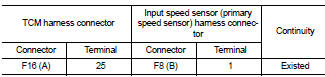
Is the inspection result normal? YES >> GO TO 9.
NO >> Repair or replace damaged parts.
9.CHECK HARNESS BETWEEN TCM AND INPUT SPEED SENSOR (PRIMARY SPEED SENSOR) (SENSOR GROUND) (PART 2)
1. Disconnect CVT unit harness connector.
2. Check continuity between TCM harness connector F16 terminal 25 and ground.
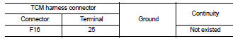
Is the inspection result normal? YES >> GO TO 10.
NO >> Repair or replace damaged parts.
10.CHECK CVT UNIT CIRCUIT
Check continuity between CVT unit harness connector F46 terminal 19 and ground.
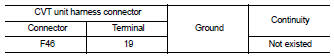
Is the inspection result normal? YES >> GO TO 11.
NO >> Repair or replace damaged parts.
11.CHECK TCM
1. Replace same type TCM. Refer to TM-430, "Exploded View".
2. Connect each connector.
3. Perform “DTC CONFIRMATION PROCEDURE”. Refer to TM-313, "DTC Logic".
Is “P0715 INPUT SPD SEN/CIRC” detected? YES >> Replace input speed sensor (primary speed sensor). Refer to TM-437, "Removal and Installation".
NO >> Replace TCM. Refer to TM-430, "Exploded View".
12.DETECT MALFUNCTIONING ITEMS
Check TCM connector pin terminals for damage or loose connection with harness connector.
Is the inspection result normal? YES >> Replace TCM. Refer to TM-430, "Exploded View".
NO >> Repair or replace damaged parts.
 P0710 CVT fluid temperature sensor
 P0720 vehicle speed sensor cvt (secondary
speed sensor)
P0720 vehicle speed sensor cvt (secondary
speed sensor)